Attempt 1
In the beginning, my plan was to attempt to reproduce HomoFaciens' design (see my research here for more about it) as it is the most easily reproduced, using only 3D printed and hardware store items.
The original maker had tweaked his original design as he went to a level where it functioned quite reliably for him even for long prints. I thought I could reproduce his design and then document & test it more completely to maybe make some improvements.
Making it:
Unfortunately, reproducing his results was not as easy as I had hoped. Rather than continuing with this design, I decided I could make better use of my time by taking what I had learned about what does/doesn’t work from reproducing this design and combining it with what I had read about more professionally made/ consumer made “granule printers” in order to create my own design.
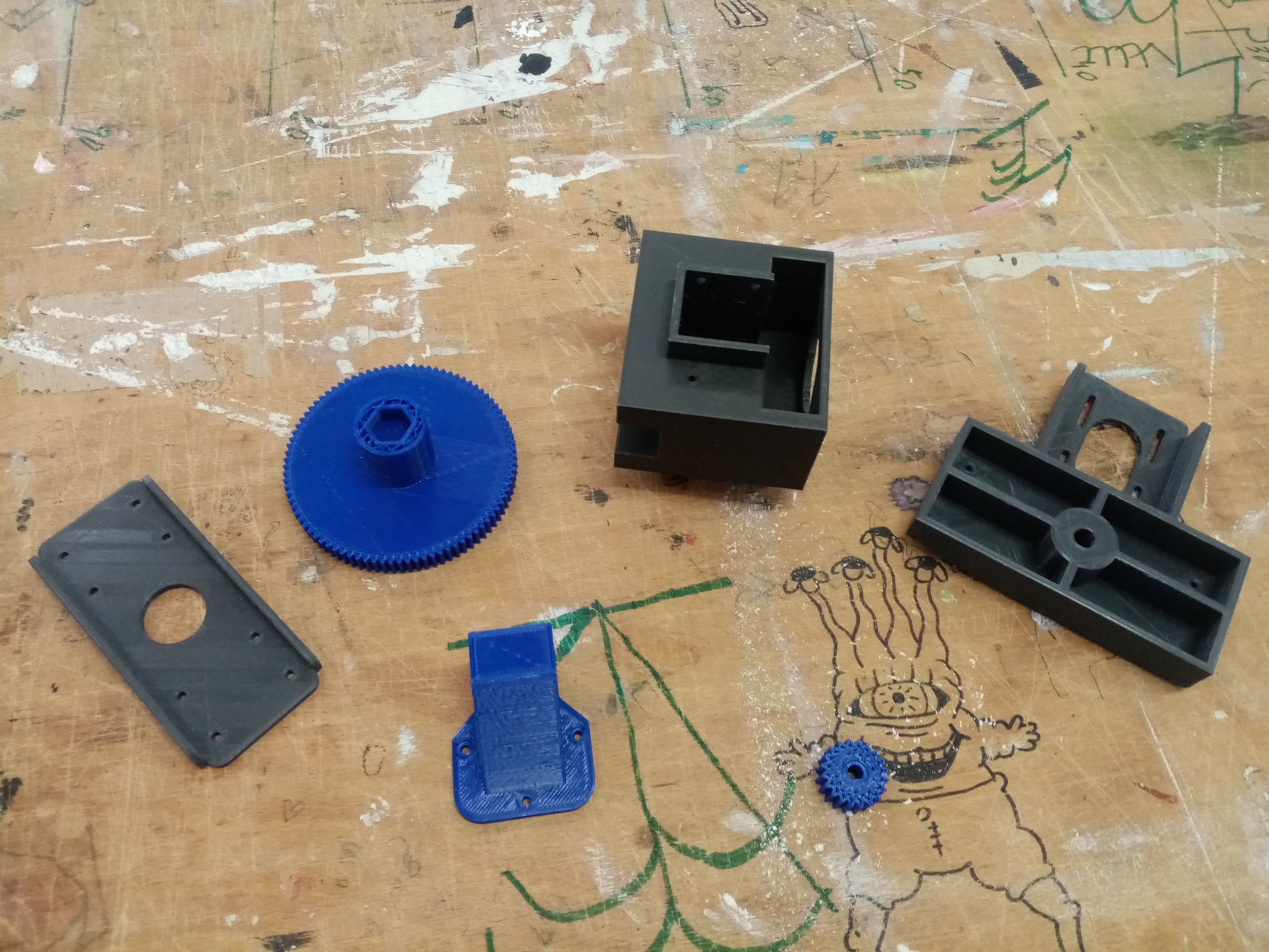
3D printed parts
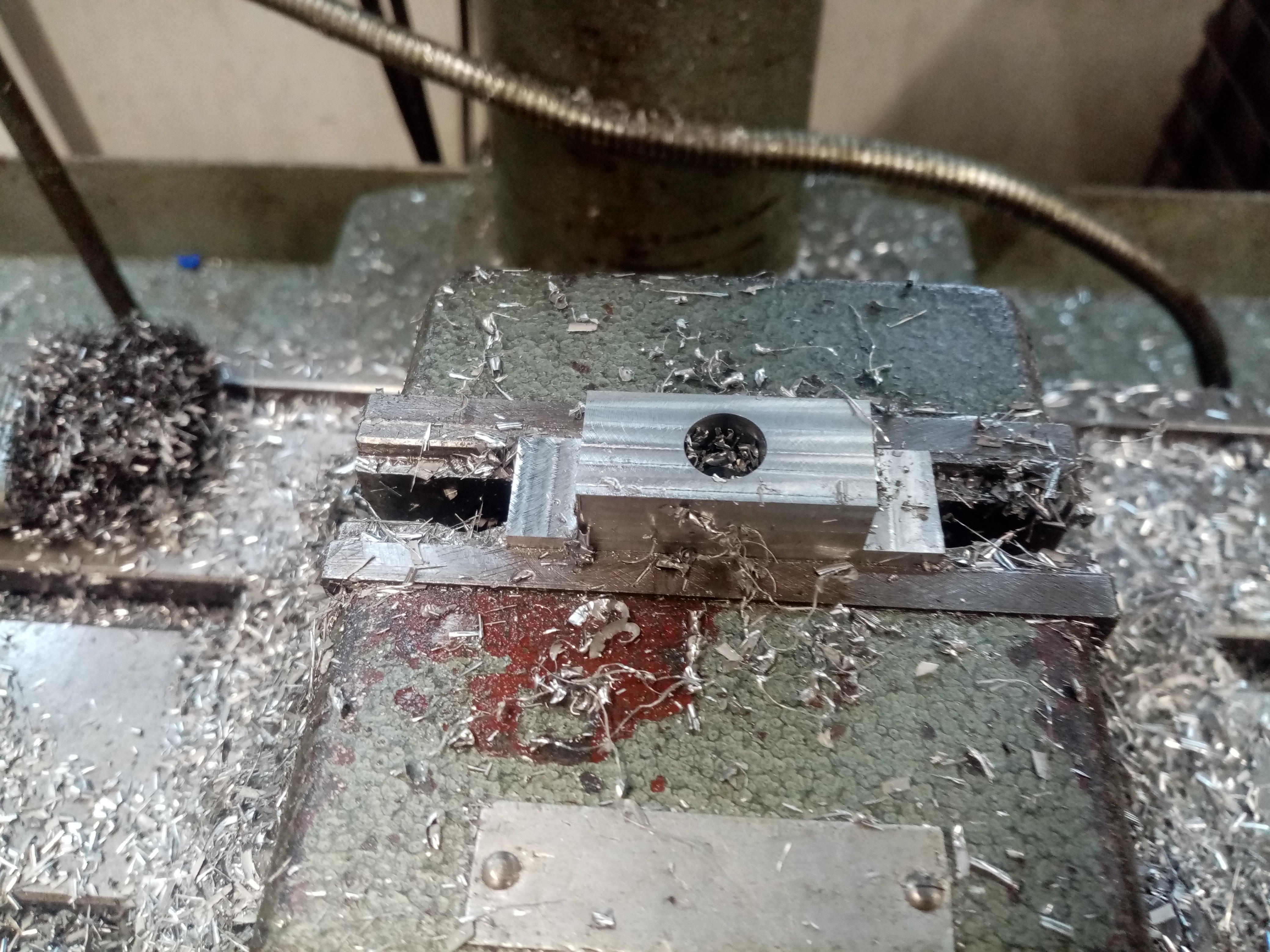
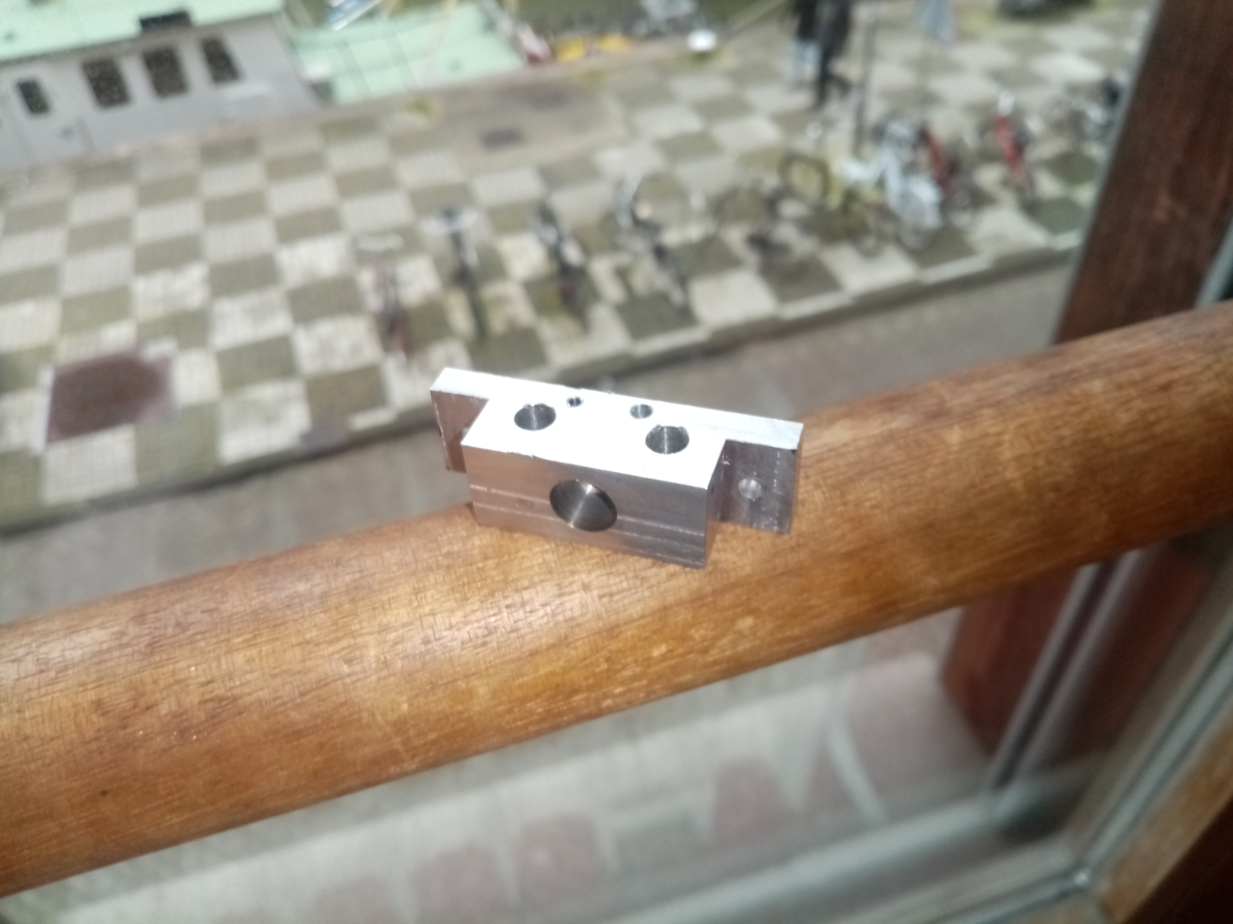
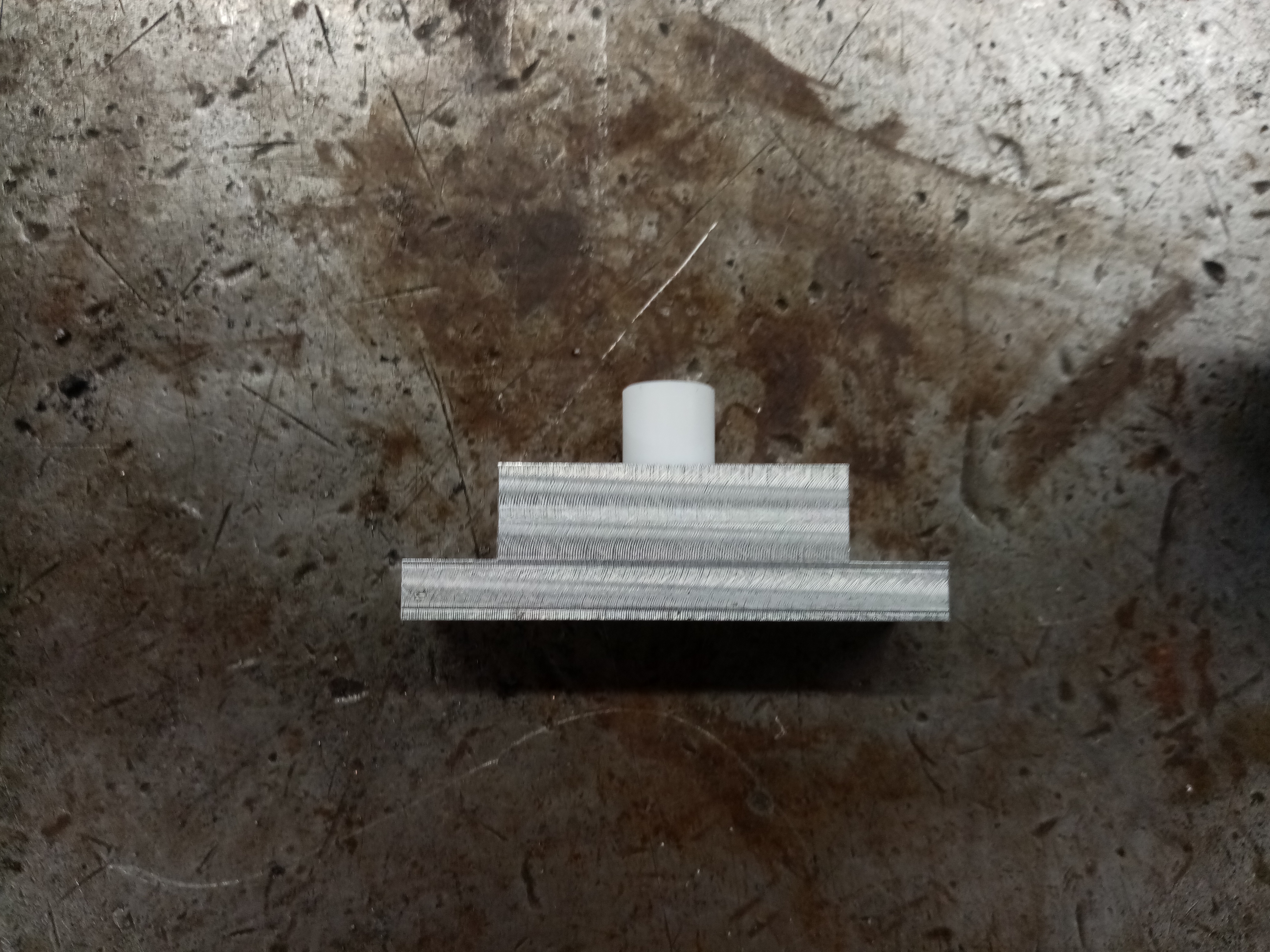
Milled aluminum parts:
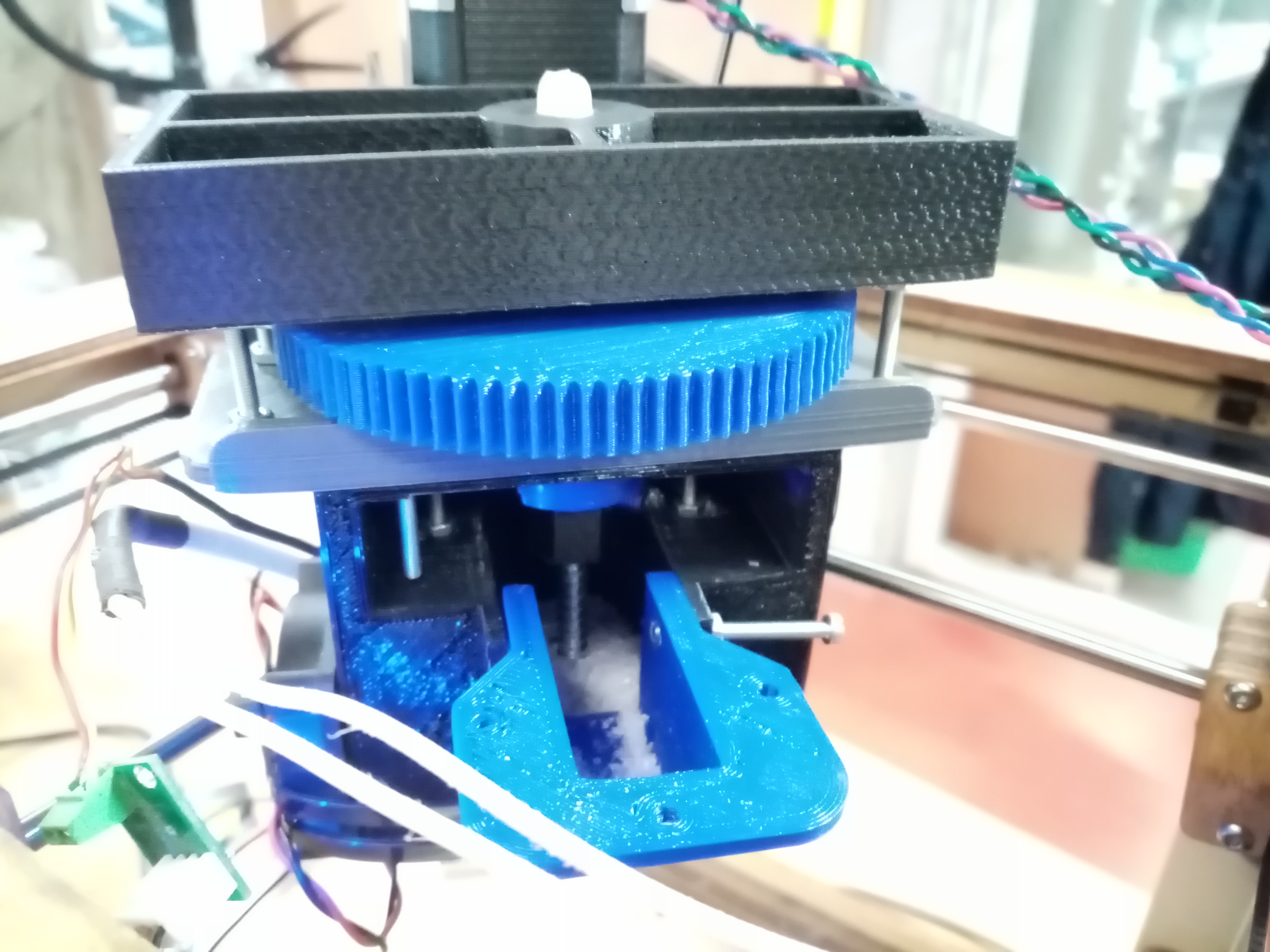
Attached to the printer and filled with plastic
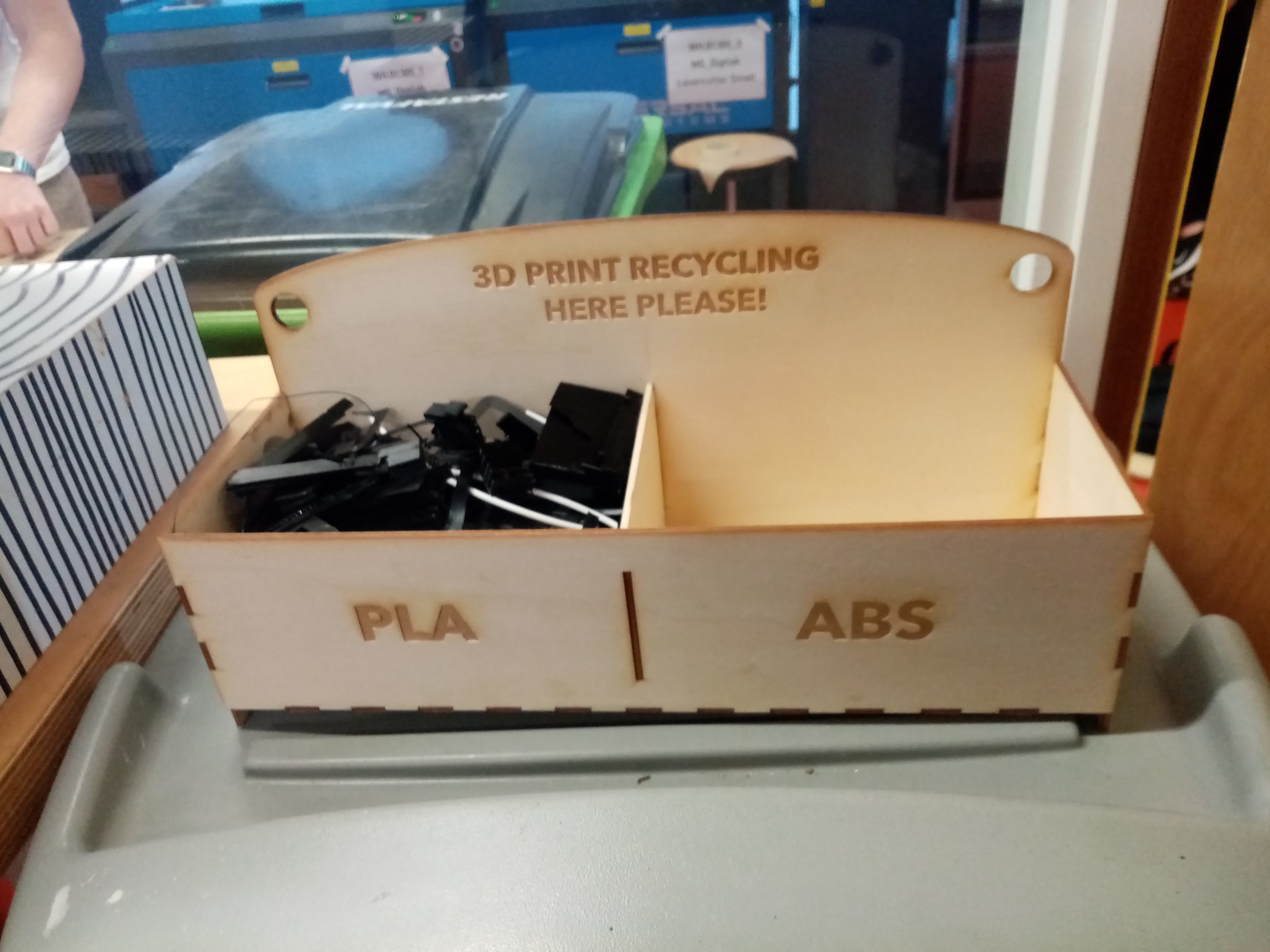
Plastic was collected from the Digital Station at WDKA for testing with the print head.
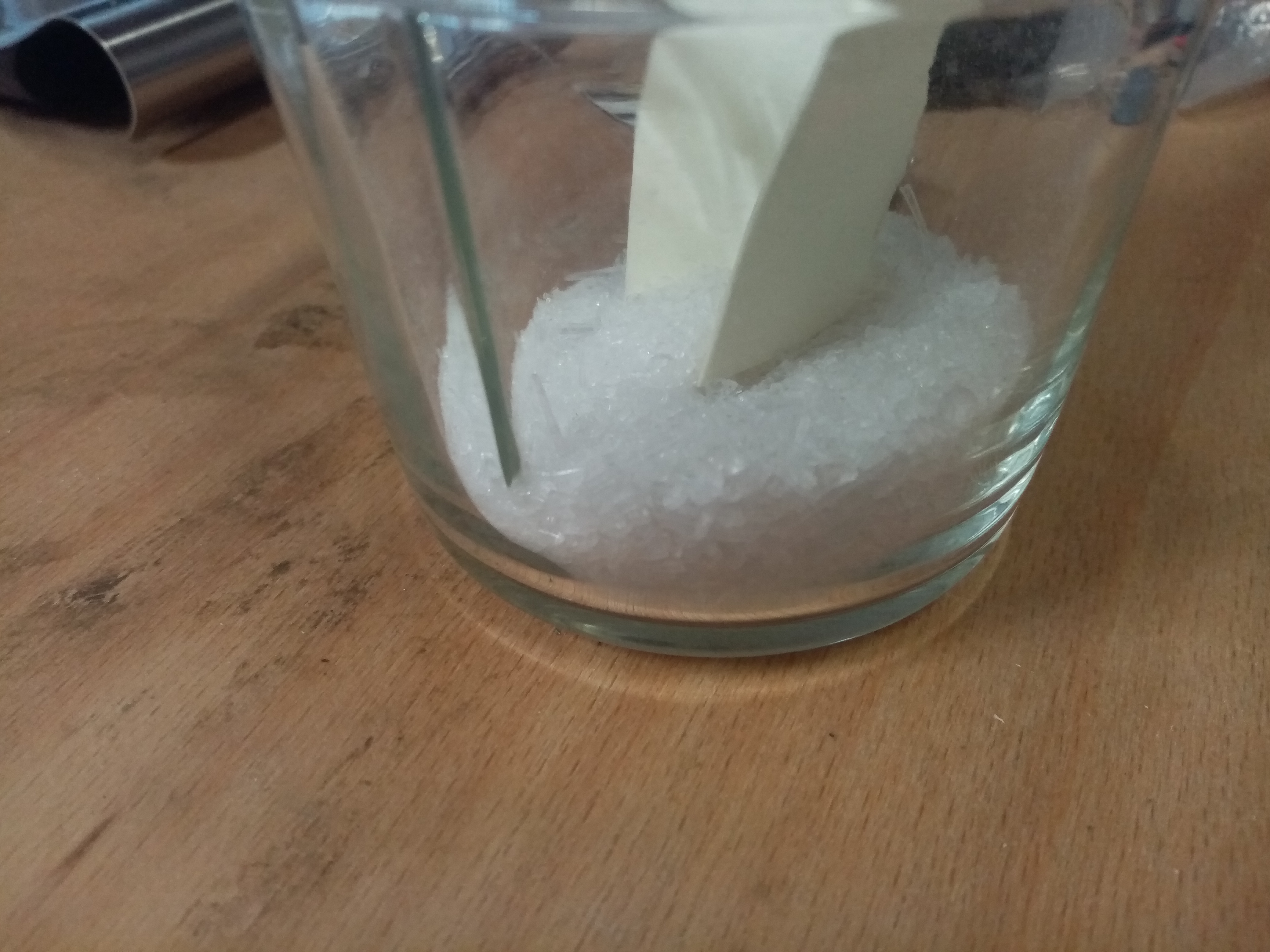 Attempts were made to print with corse (approx.3mm) ground plastic.
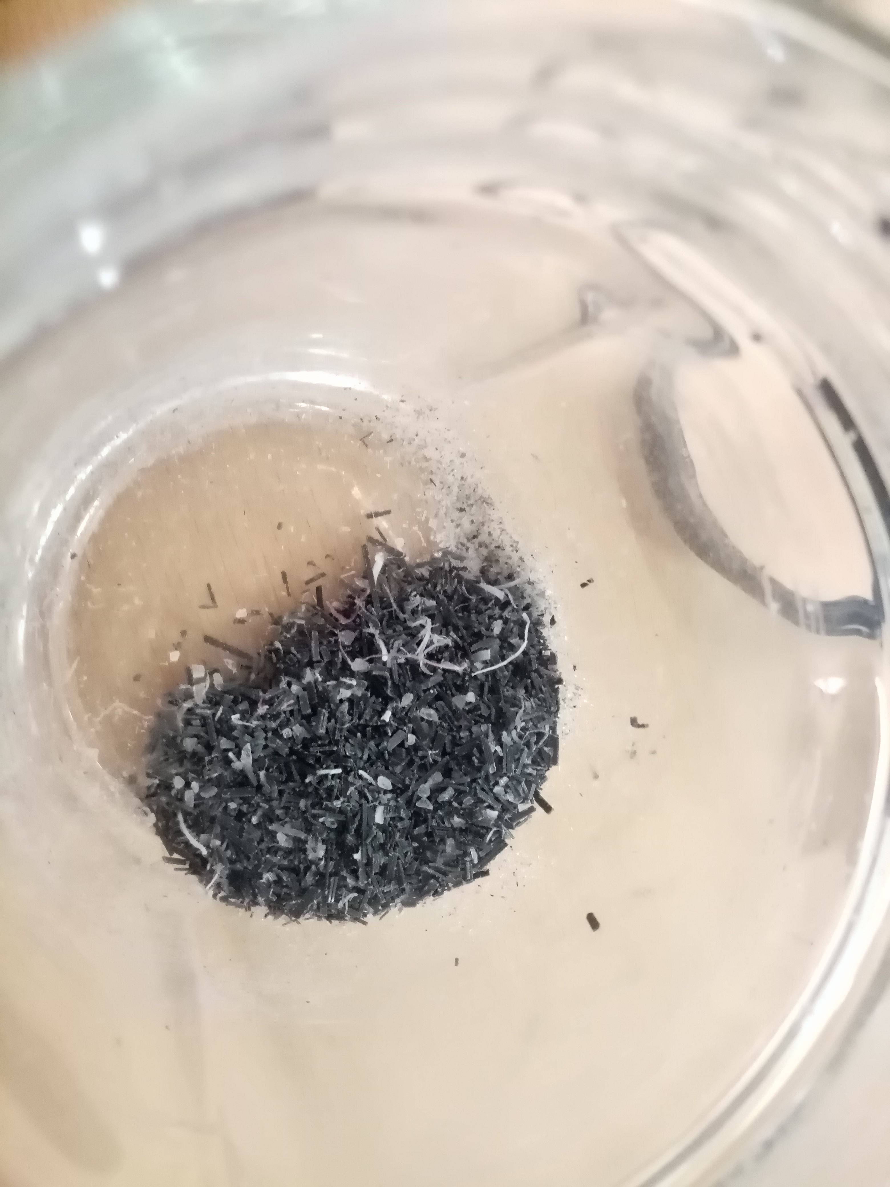 Also tried was much finer plastic, obtained by passing the grounds through a sieve
 On both attempts no plastic was extruded through the nozzle.
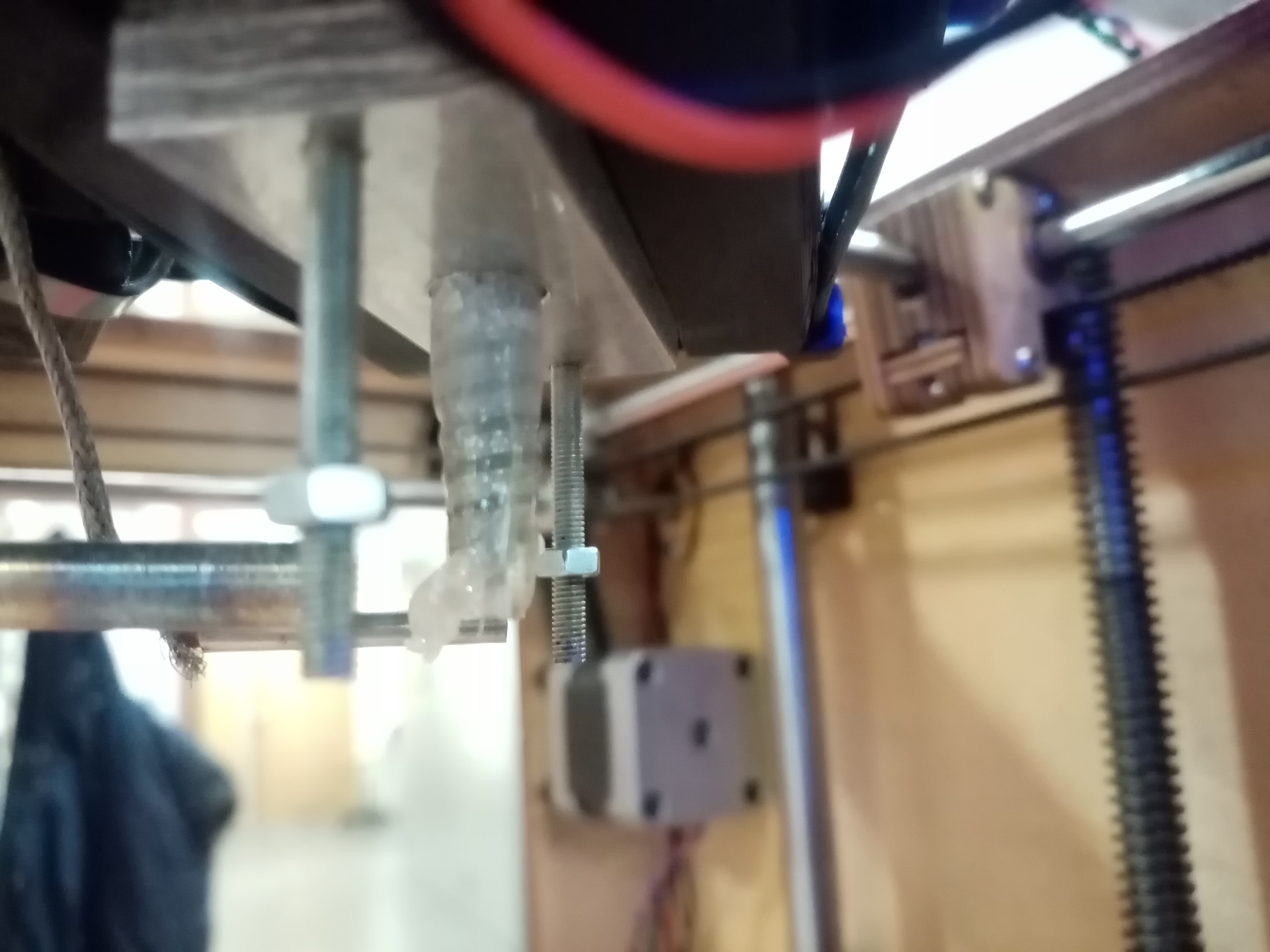 When the heating block was removed it was clear that the plastic had melted but was not pushed through the nozzle. I think this has to do with the screw being a smaller diameter than the 8mm melting chamber, allowing the plastic to flow back upwards around the screw threads.
An attempt was made using a snug fitting, 8mm drill bit which extruded for a moment before becoming clogged. The clogging, I think, was caused by the heat travelling up and melting the plastic slightly at the top of the heating chamber.
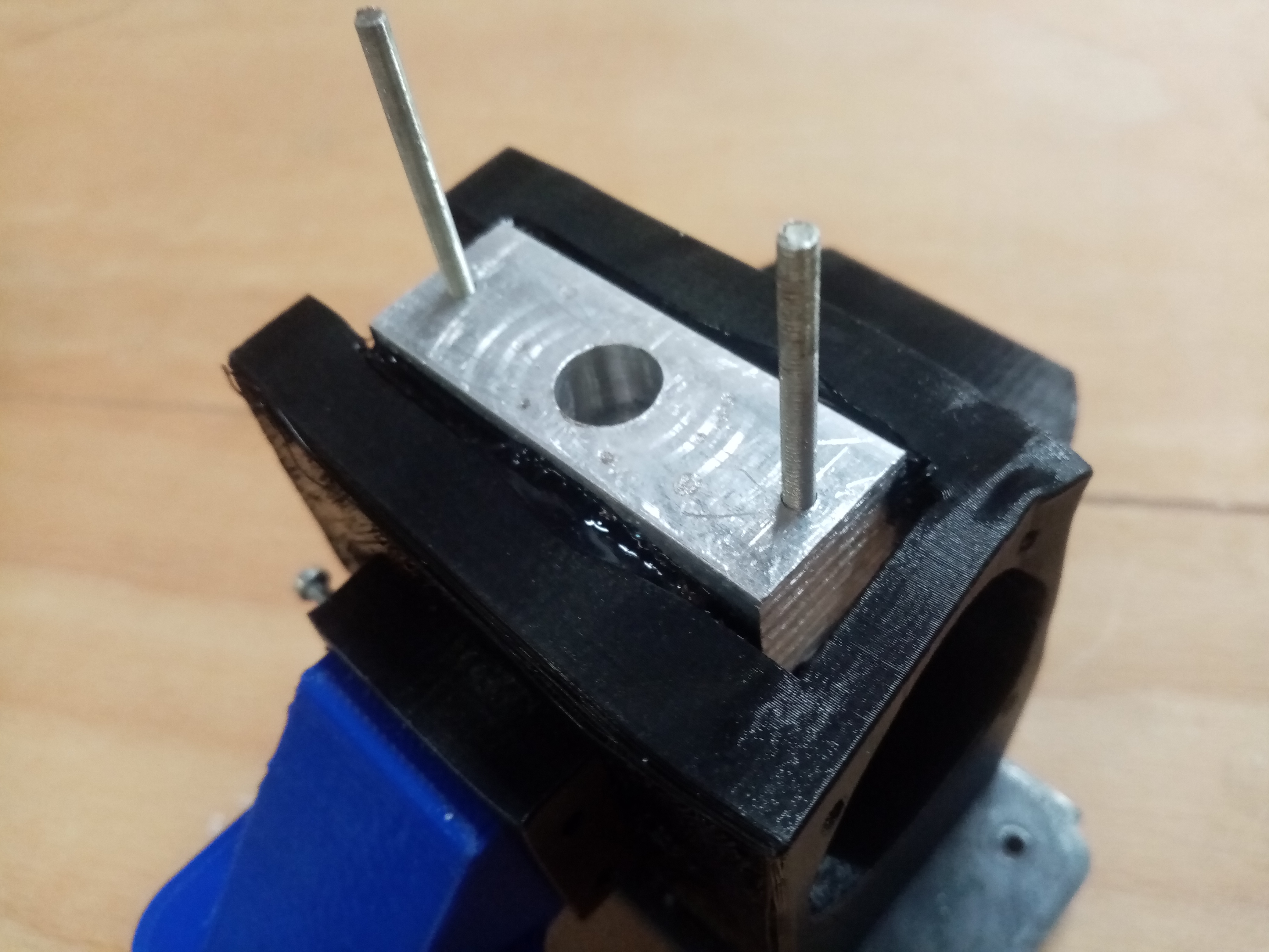
I attempted to add more cooling with aluminium sheets between the heating chamber and the rest of the printer head but the heat still travelled up, enough to partially melt the so called “cold end” into the 3D printed hopper piece.
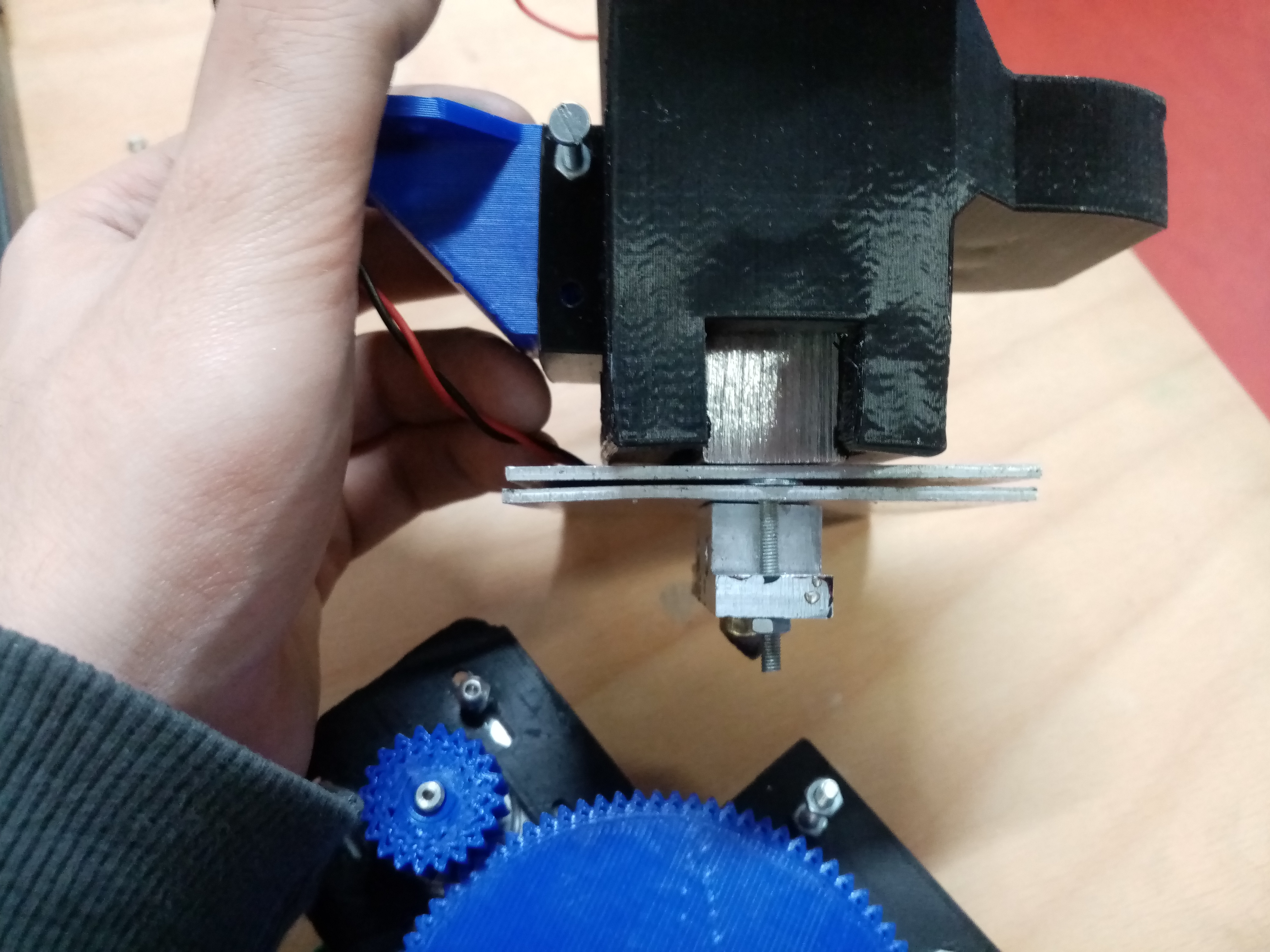
I think the closeness of the heating chamber and the cold end is the downfall of this design. The original designer seems to have progressively added cooling between the hot and cold end until this problem was solved. The resulting heatsink was quite big and unwieldy. I have no doubt that with more tweaking I could have eventually gotten this design to work as he did.
I decided I would switch my approach and attempt to take one of these existing designs and make it more easily reproducible for others, instead of taking an already firmly D.I.Y.-ish design and trying to improve on it. This way I can work from existing designs which have research and good documentation as a guide. These designs are typically expensive or complicated to reproduce because of the creators' goal involving the ability to produce low tolerance parts which fit together with their design. I and many others in art and design don’t require this level of accuracy, who cares if your bowl or sculpture is 1mm off the measurement? Especially if what you are printing has been designed with those loose tolerances in mind from the beginning. I see a fertile niche for a designer like myself to take these more engineered designs and make them more easily.
This lead me to my second attempt…
Attempt 2
For attempt 2 I decided to work in the opposite rationale as before. With attempt 1, I found the most simple and reproducible existing design for a granule printer and tried to reproduce it. The problem with this approach, I think, was that the more D.I.Y versions are less refined and are less likely to work when reproduced. I made the mistake of choosing a design which has only been built once before by the creator.
This time I decided to work from a more developed prototype made using more advanced materials and machines and then work backwards from that to something that I can make myself and then later into something more reproducible.
I chose an example from TU Delft which they got to work. They used a CNC lathe to make a custom screw to push the plastic which I couldn’t replicate so I purchased this screw from a Chinese seller which was originally manufactured for a commercial pellet extruder
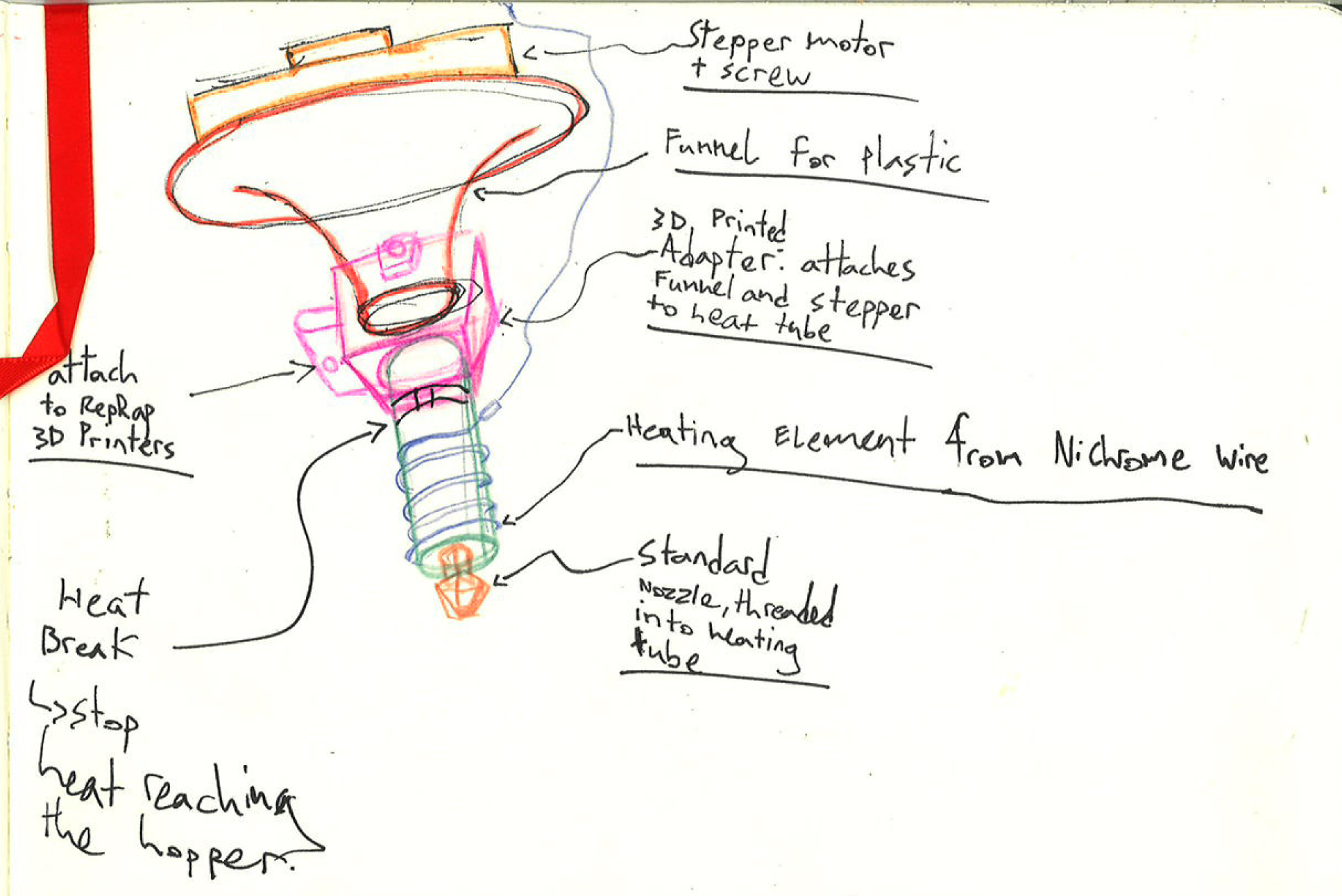
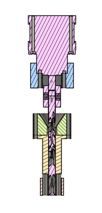
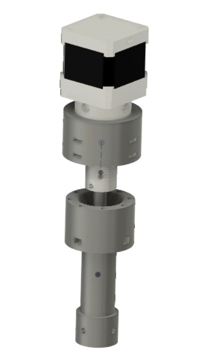
The prototype design I came up with is based on the TU Delft design and a few commercial examples. I modified it with the focus of being more suitable for attaching to a RepRap 3D printer.
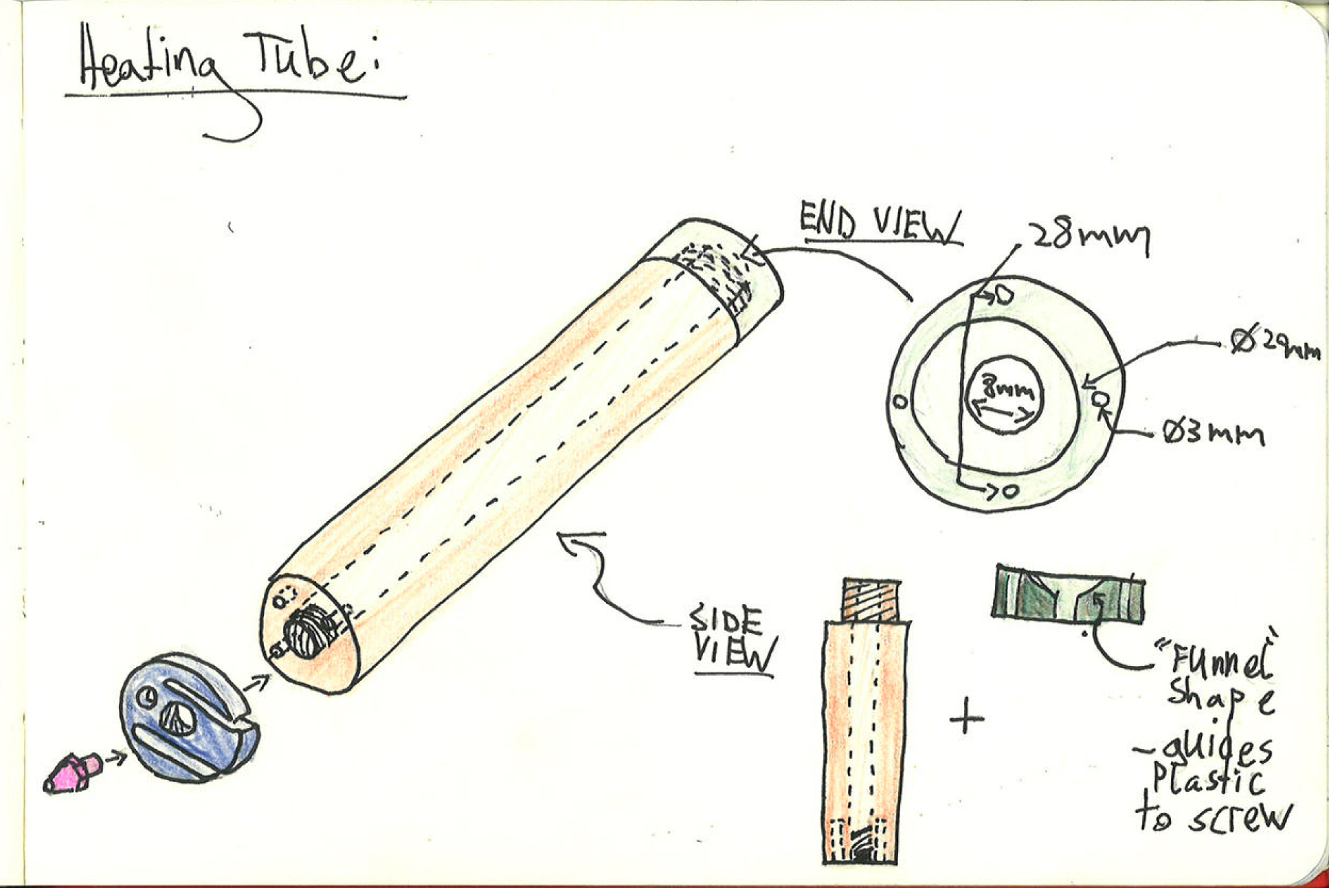
First sketches:
3D model in Fusion 360:
.STEP 3D model file download here
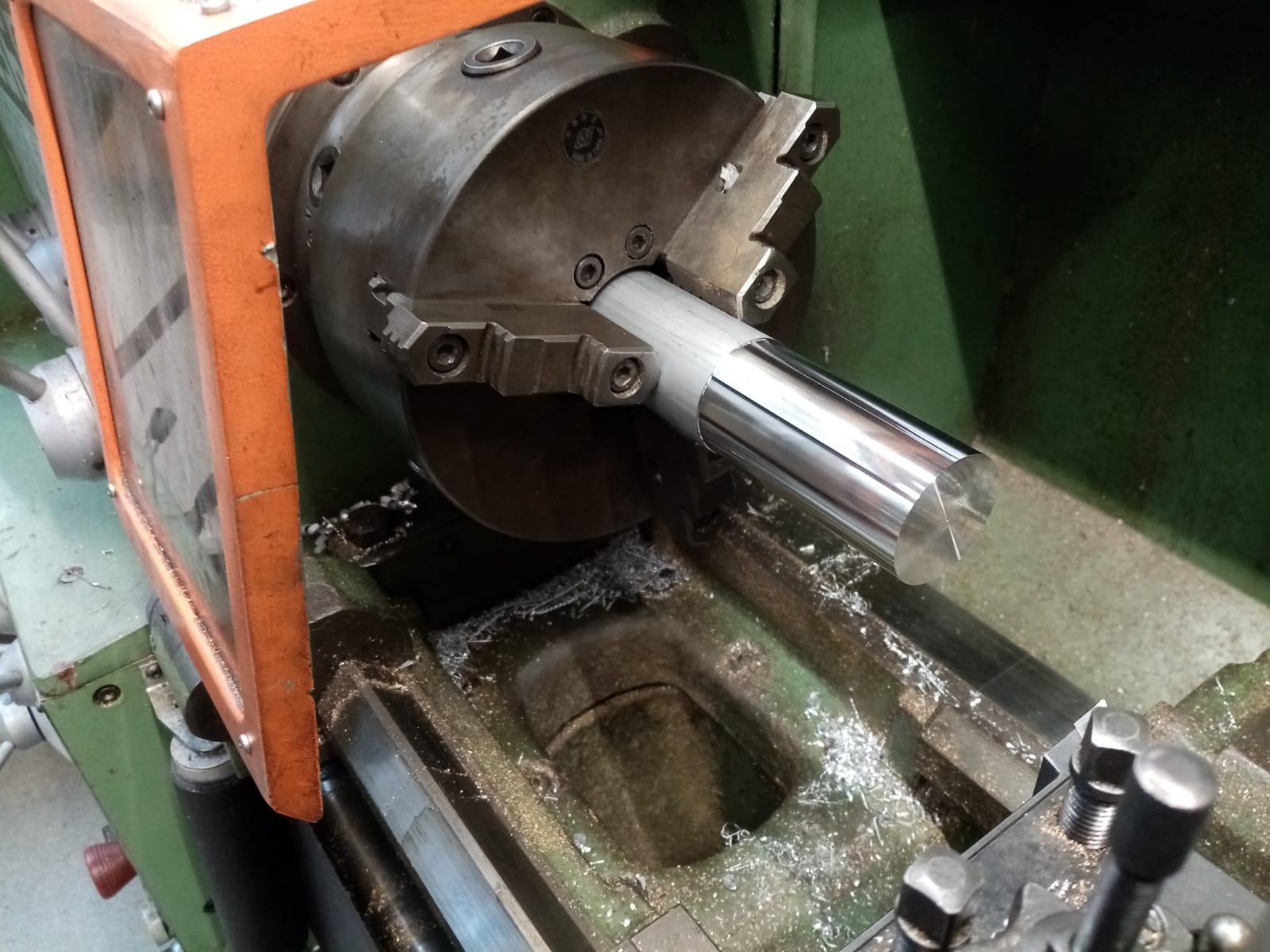
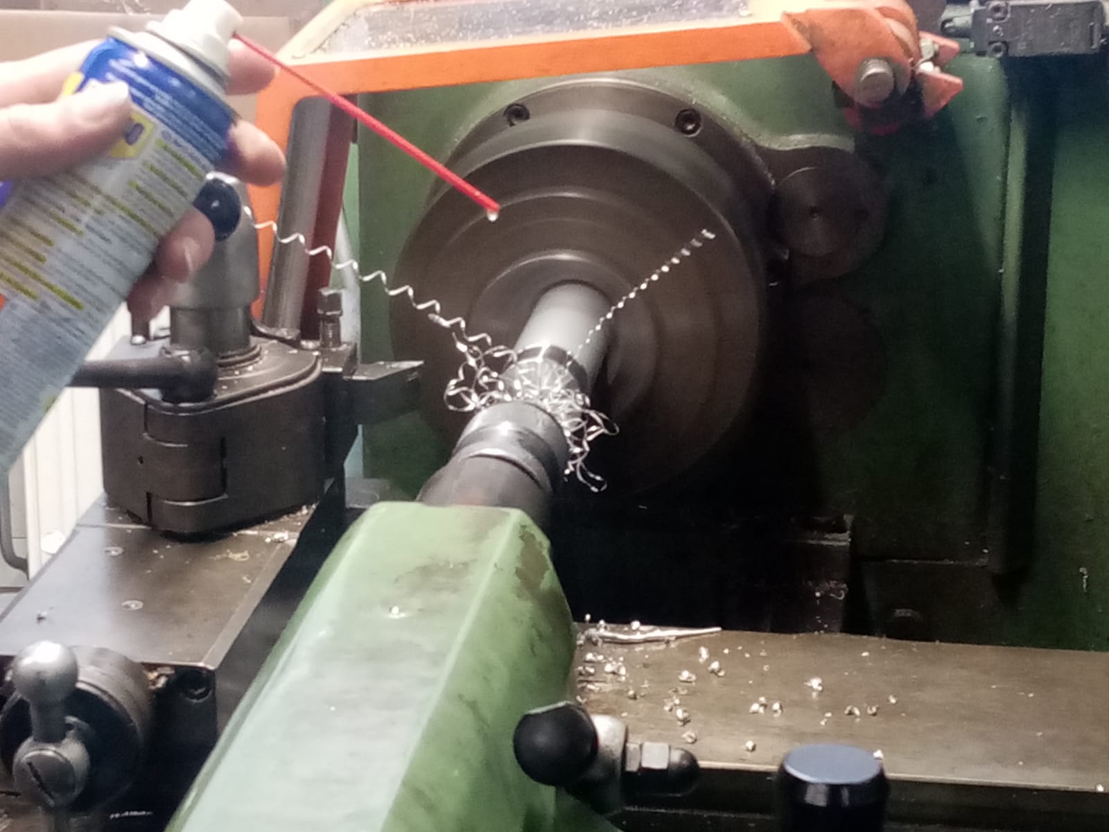
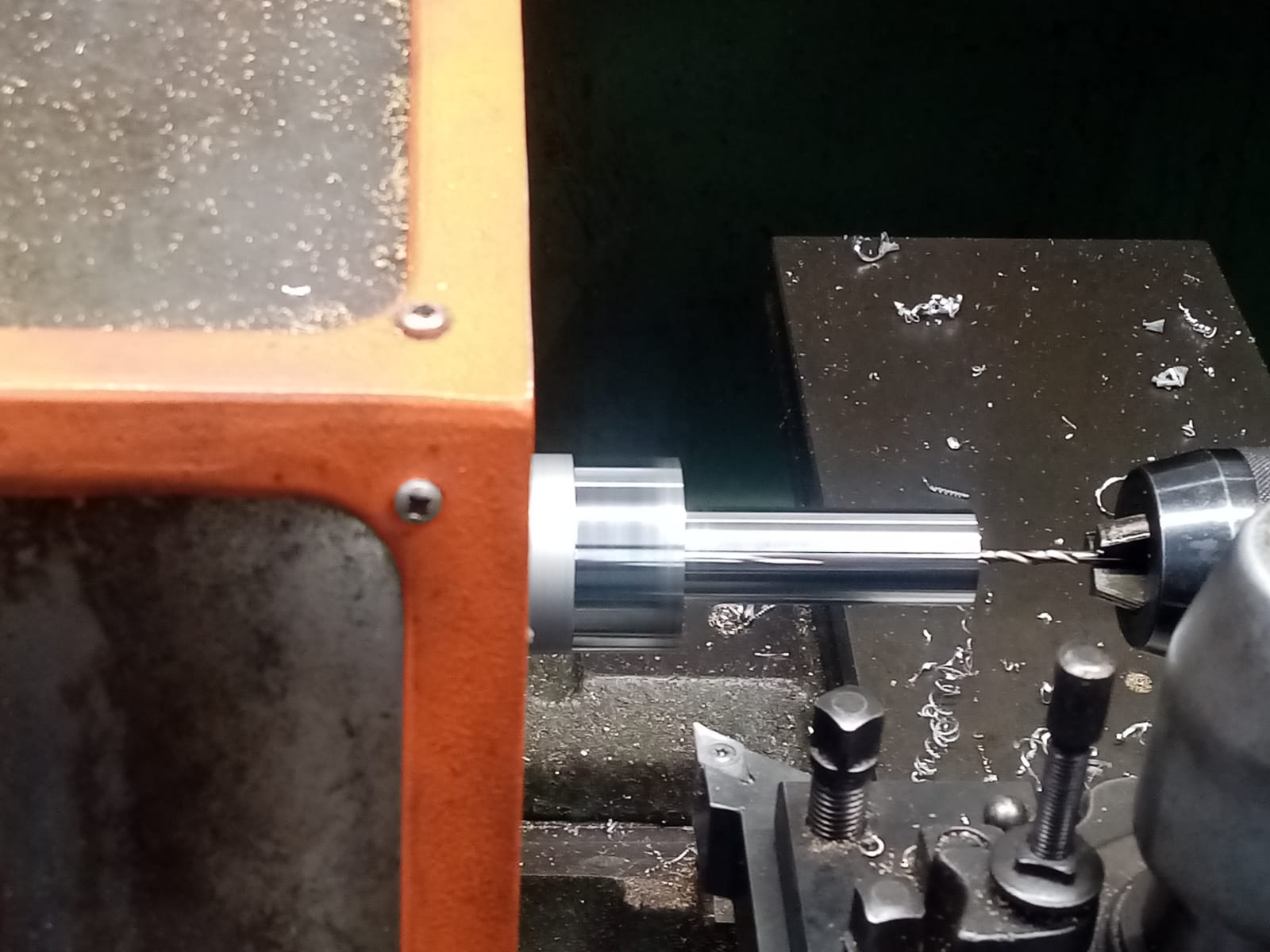
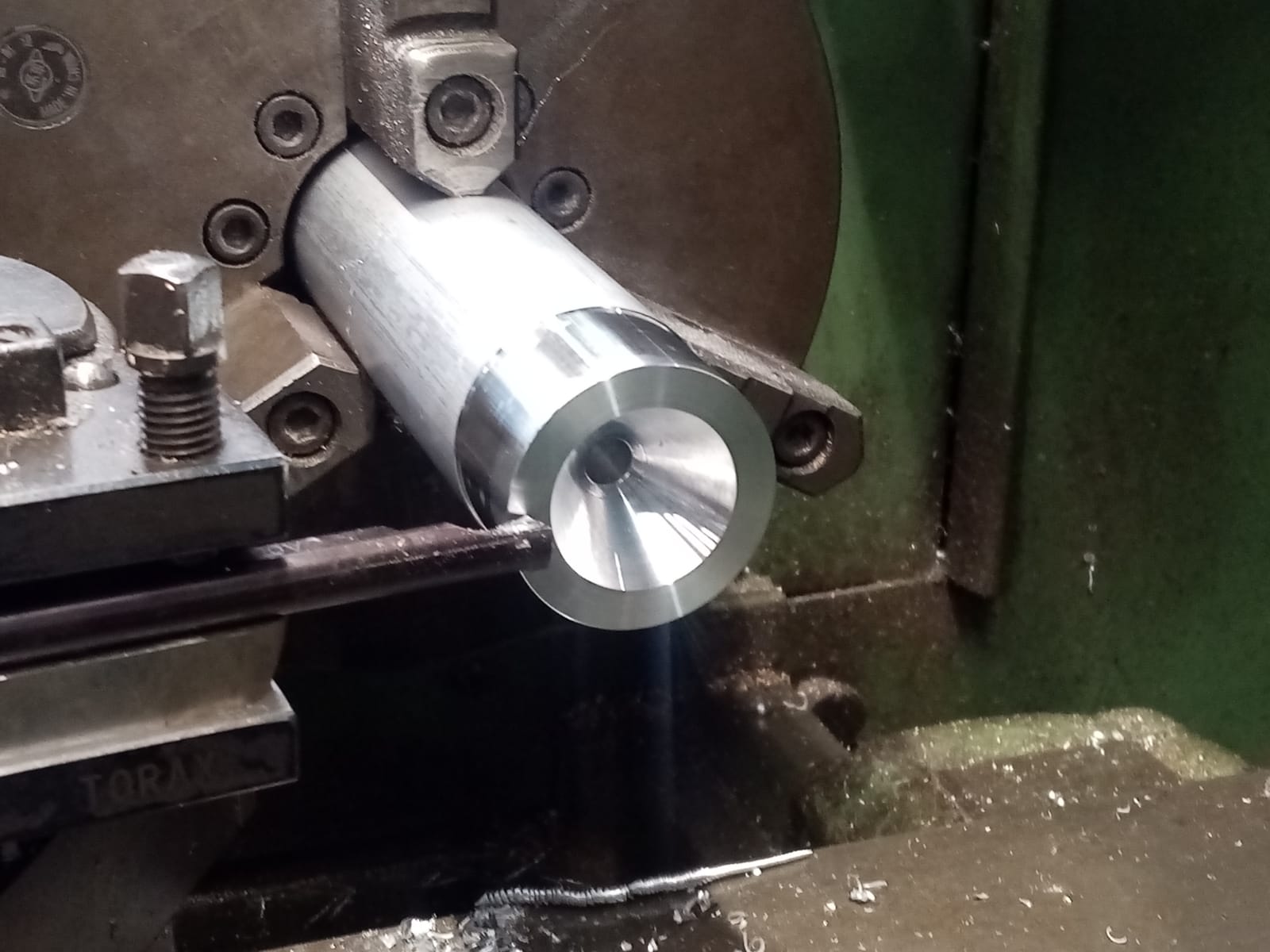
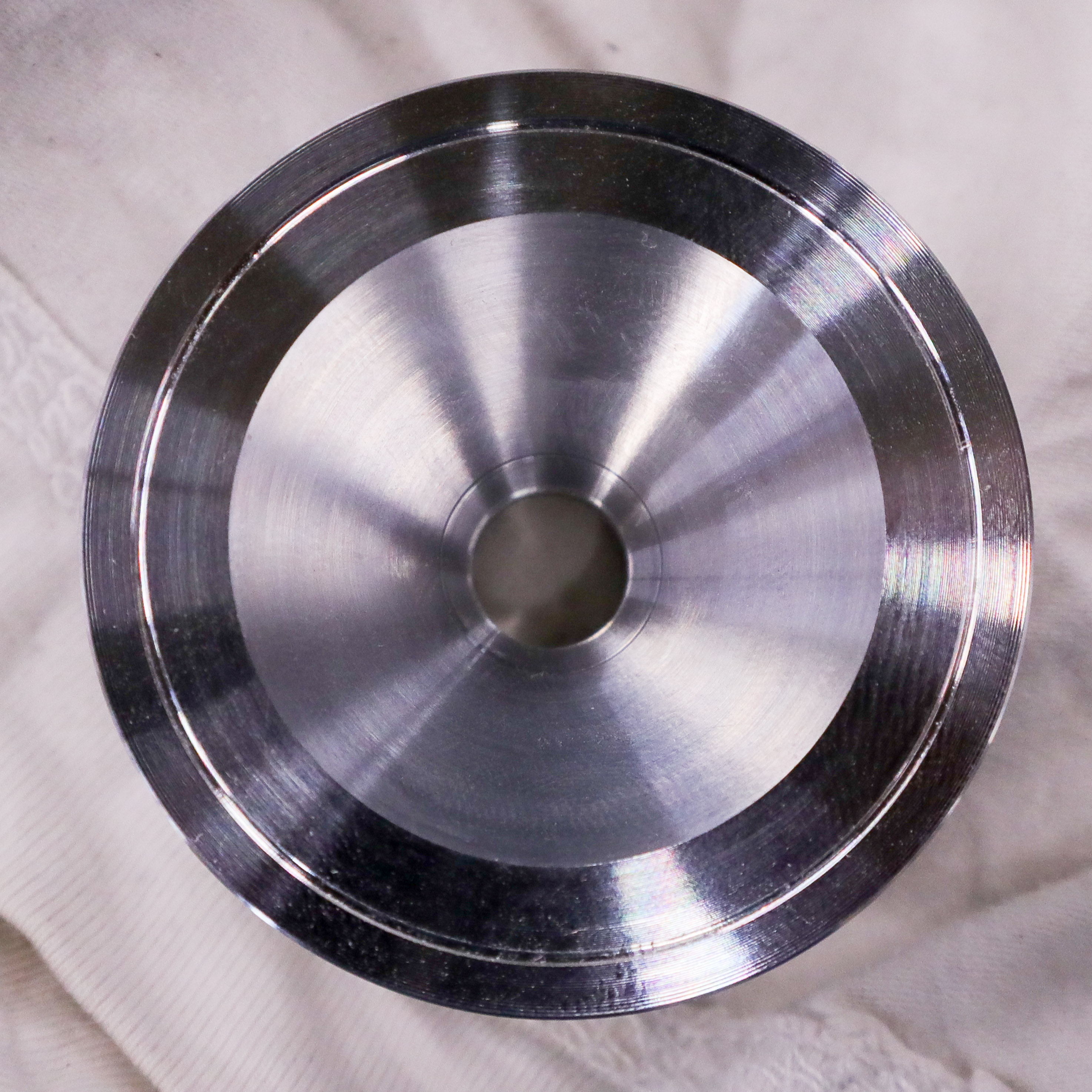
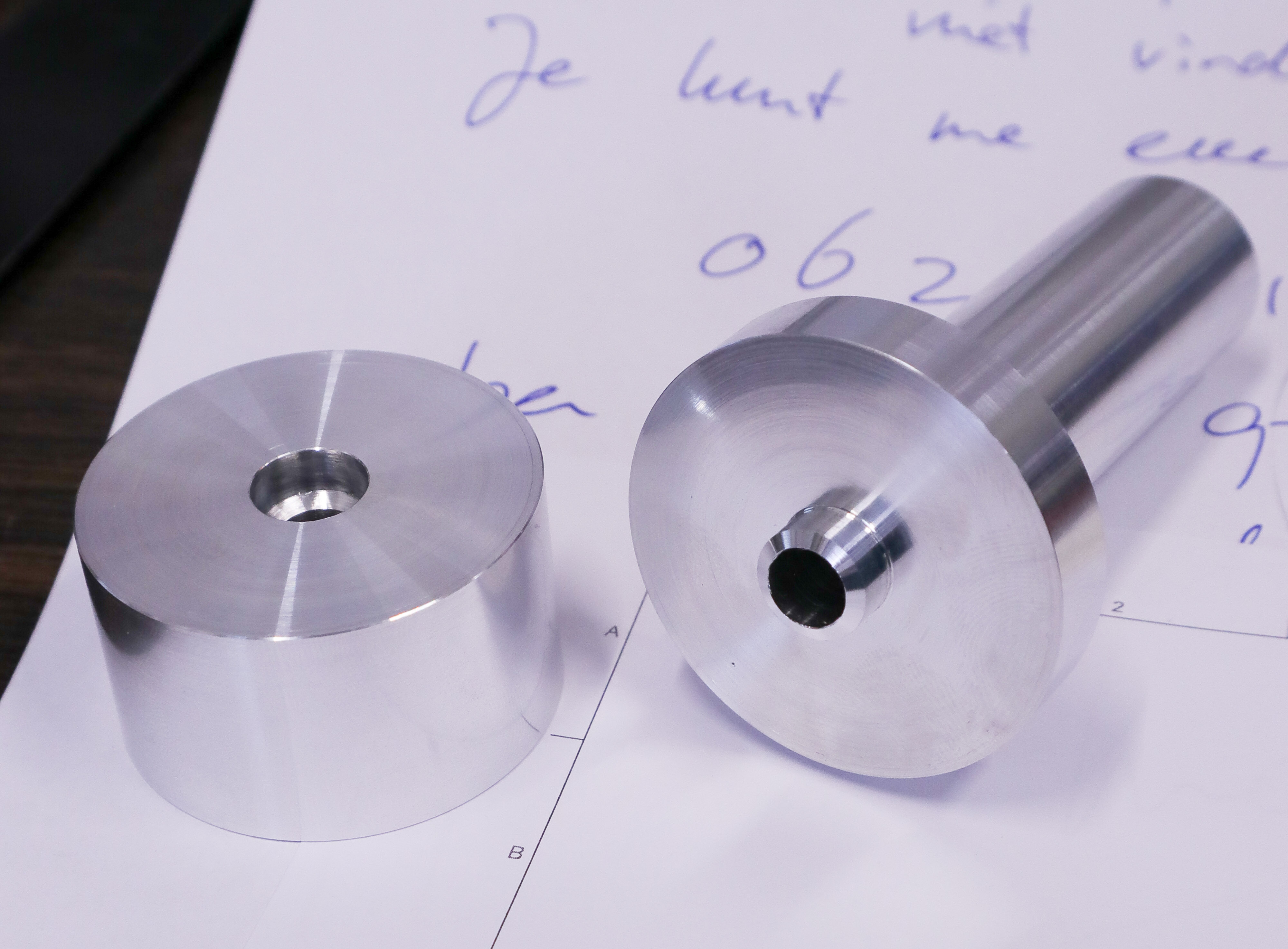
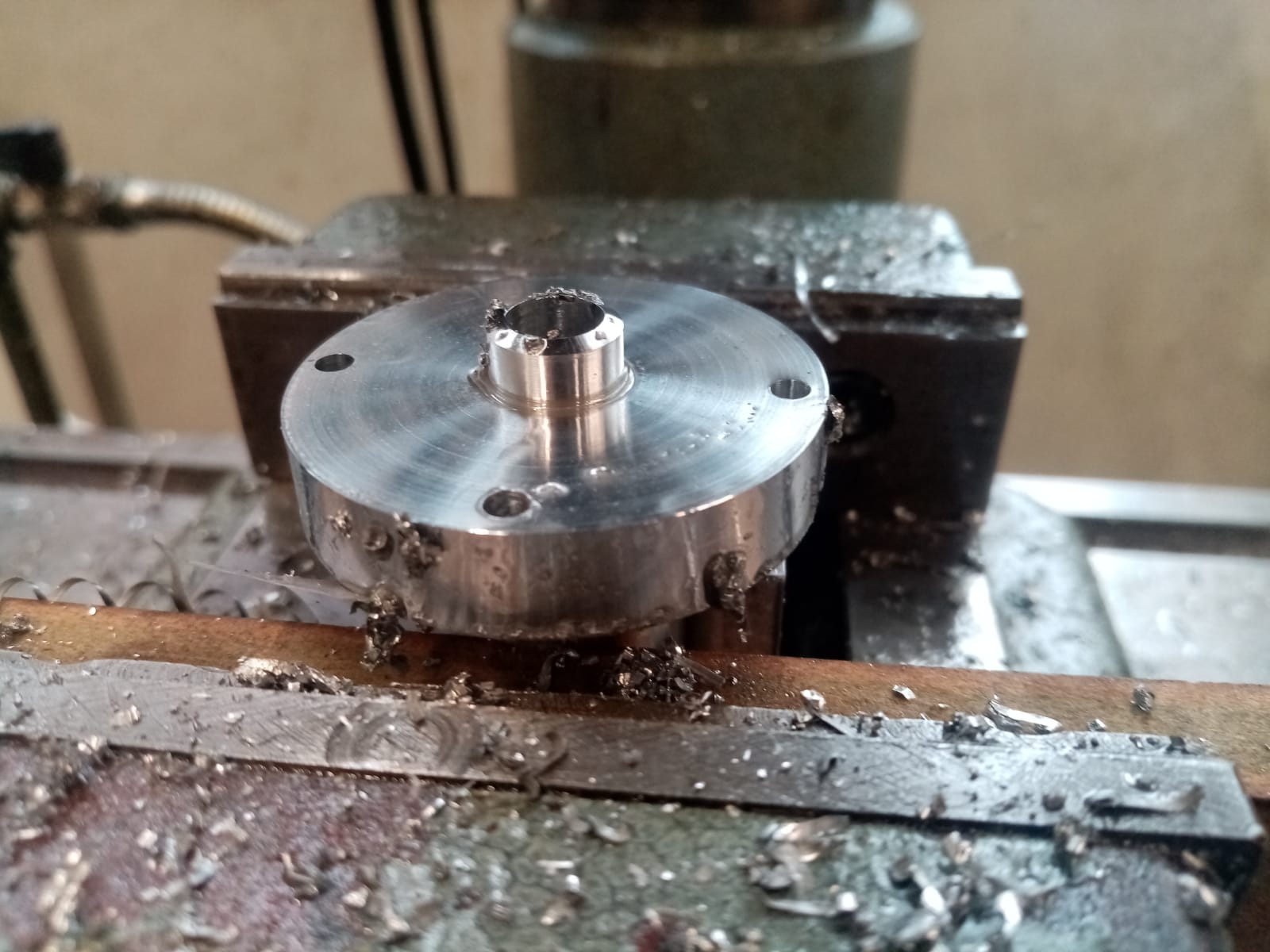
Making the prototype at the metal workshop:
Testing
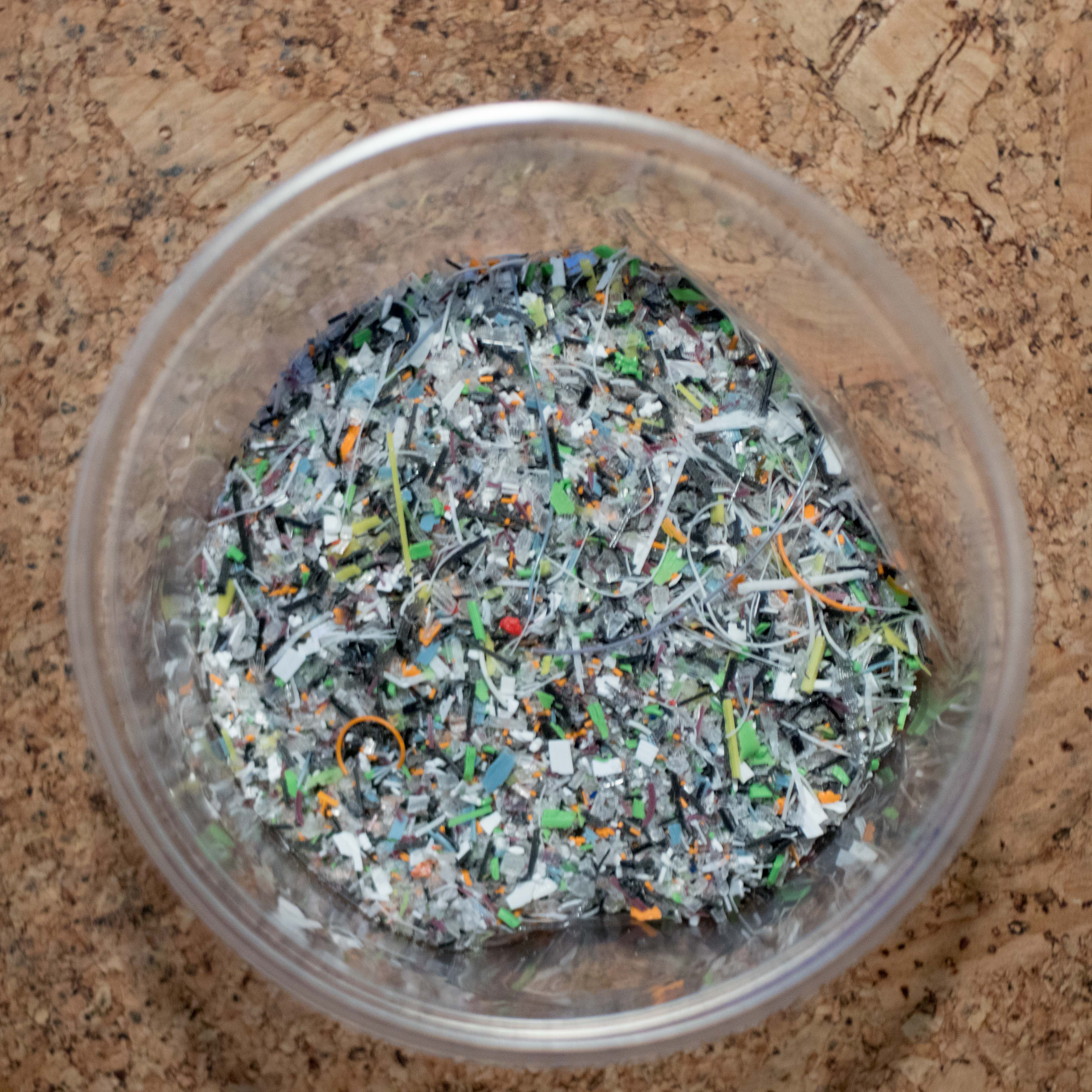
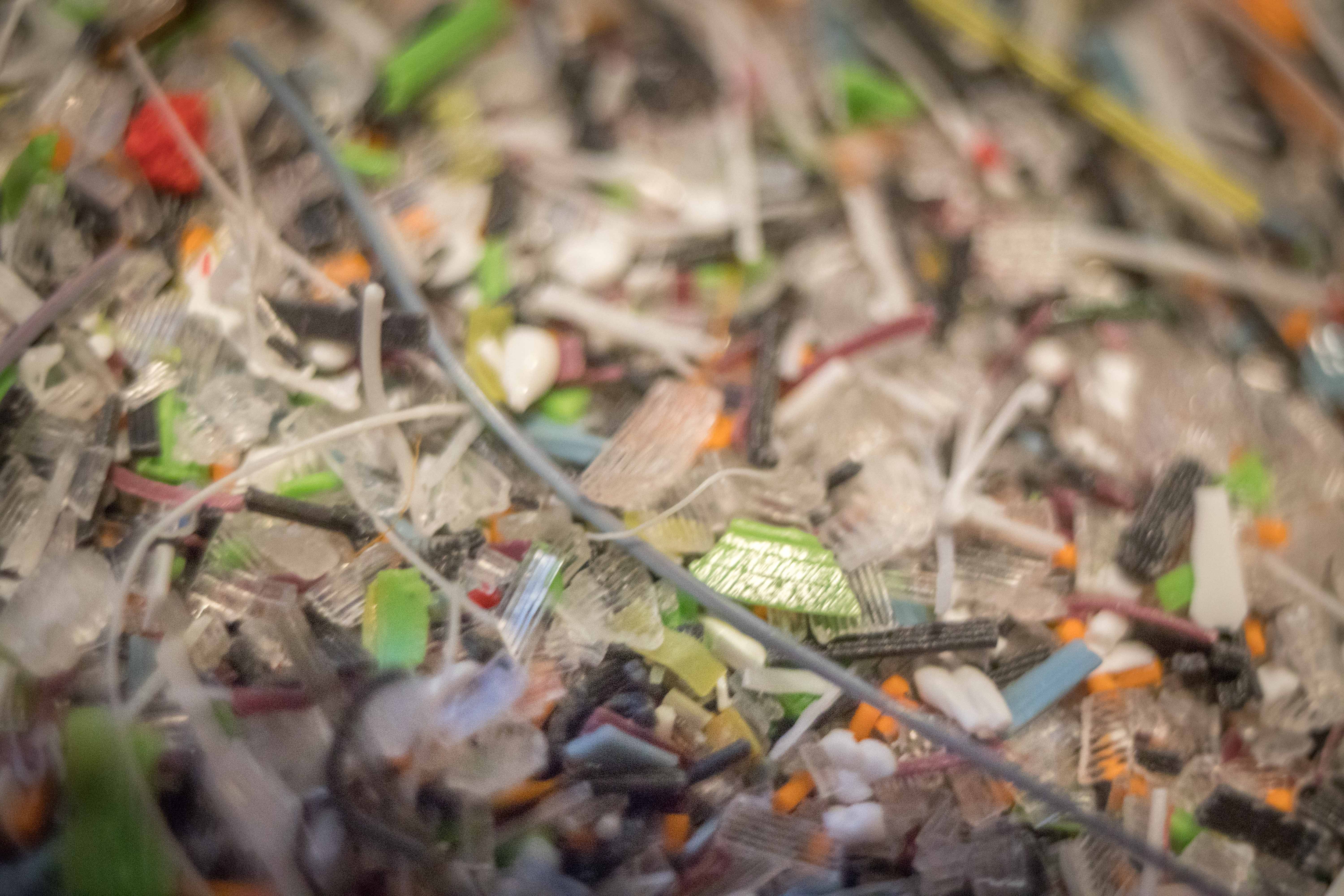
The plastic used for testing:
For the first test I used PLA of mixed colours and manufacturers. This was collected from 3D printer waste created by students at the academy.
I chose to use the PLA over the HDPE for the first test because of its lower melting temperature which should give the best chance of at least some extrusion.
This plastic was blended with a home blender and then passed through a 5mm sieve. The blending wasn’t that uniform and contained particles from the size of fine dust as well as thin strings which still managed to pass through the sieve. I will have to improve the shredding process.
Test setup:
The extruder was attached with cable ties to my 3D printers standard print head for the testing.
My printers standard 30 Watt heater as well as a 50 Watt heater cartridge were used along with the standard temperature sensor.
In order to make my extruder’s motor turn anticlockwise so that it pushes the plastic towards the nozzle instead of the stock clockwise. I did this by removing the white plastic connector for the motor from the motherboard and then connecting the motors plug to the pins directly, but in the opposite direction to normal. You could alternatively do this by editing the firmware.
A 1mm steel nozzle was used.
The following settings were used in simplify3D, the 3D print slicing software (this takes the 3D model and “slices” it into movements for the printer to make in order to print the model) I used:
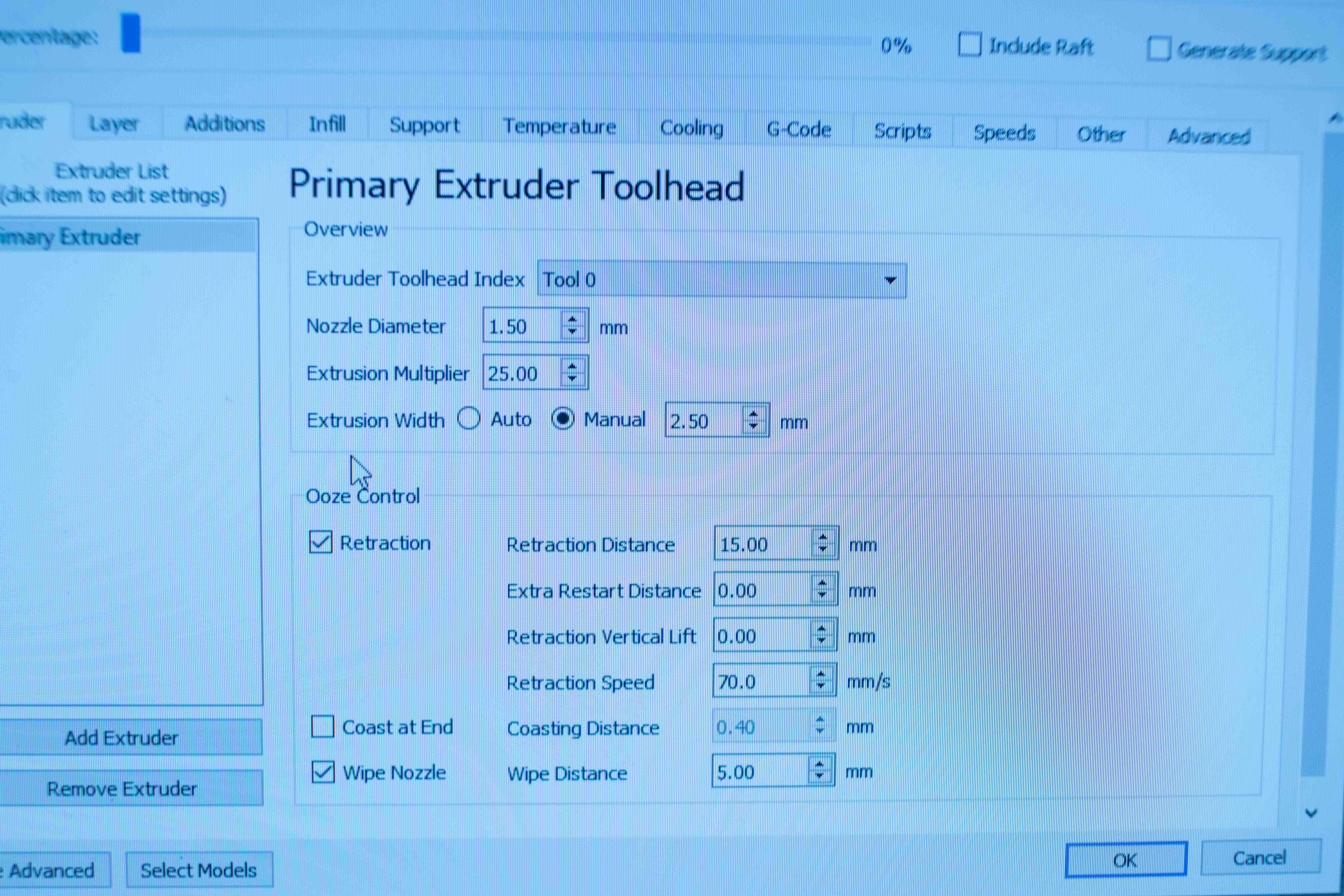
                *Not visible above:

                Layer height = 1mm

                Speed = 5mm/s
I printed a random vase with this setting and disconnected the x axis of the printer so the print head wouldn’t move. I then moved the z axis, with the printer head, slightly above the bed in order to view the nozzle easily and allow some length of plastic to extrude.
First Test
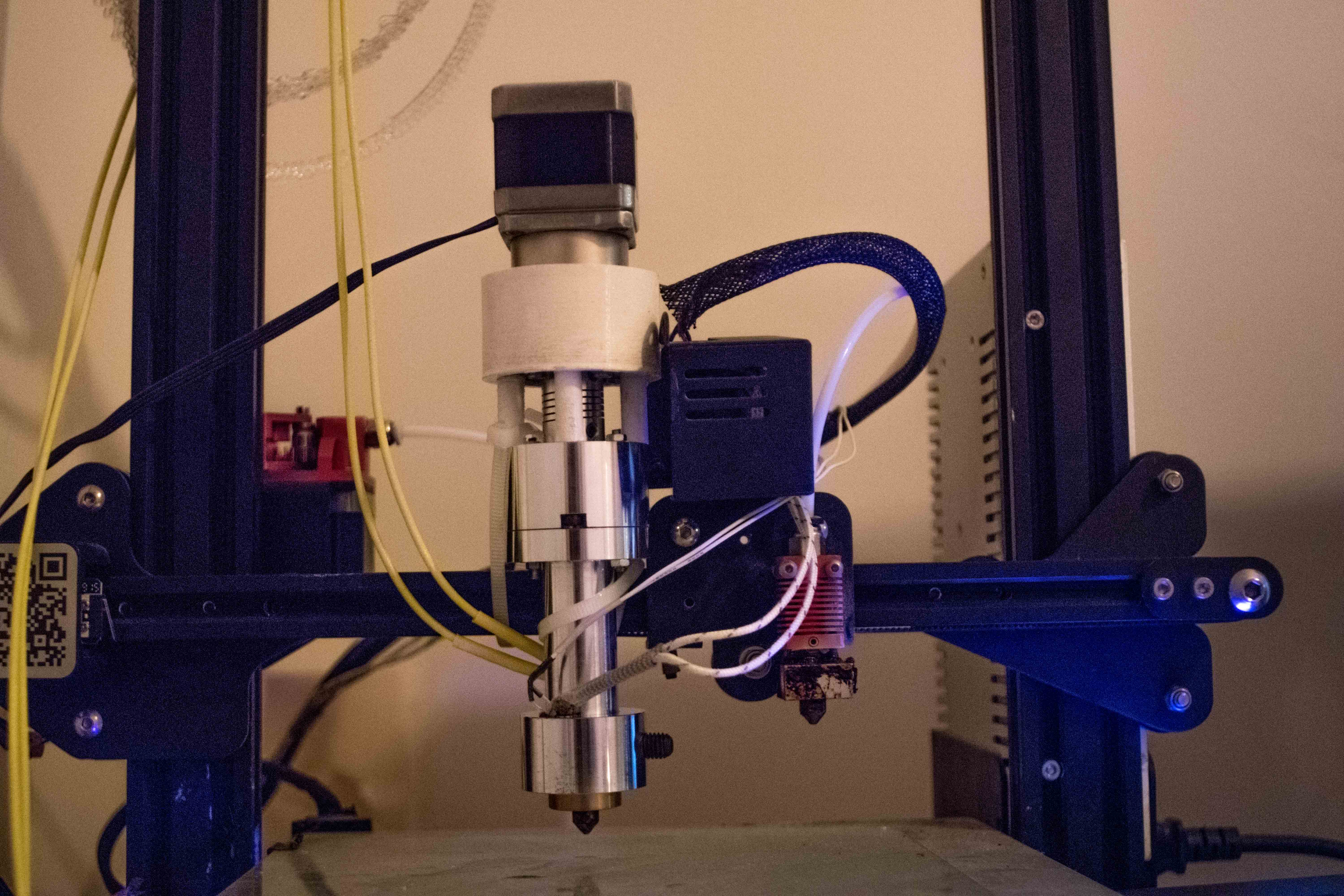
Result:
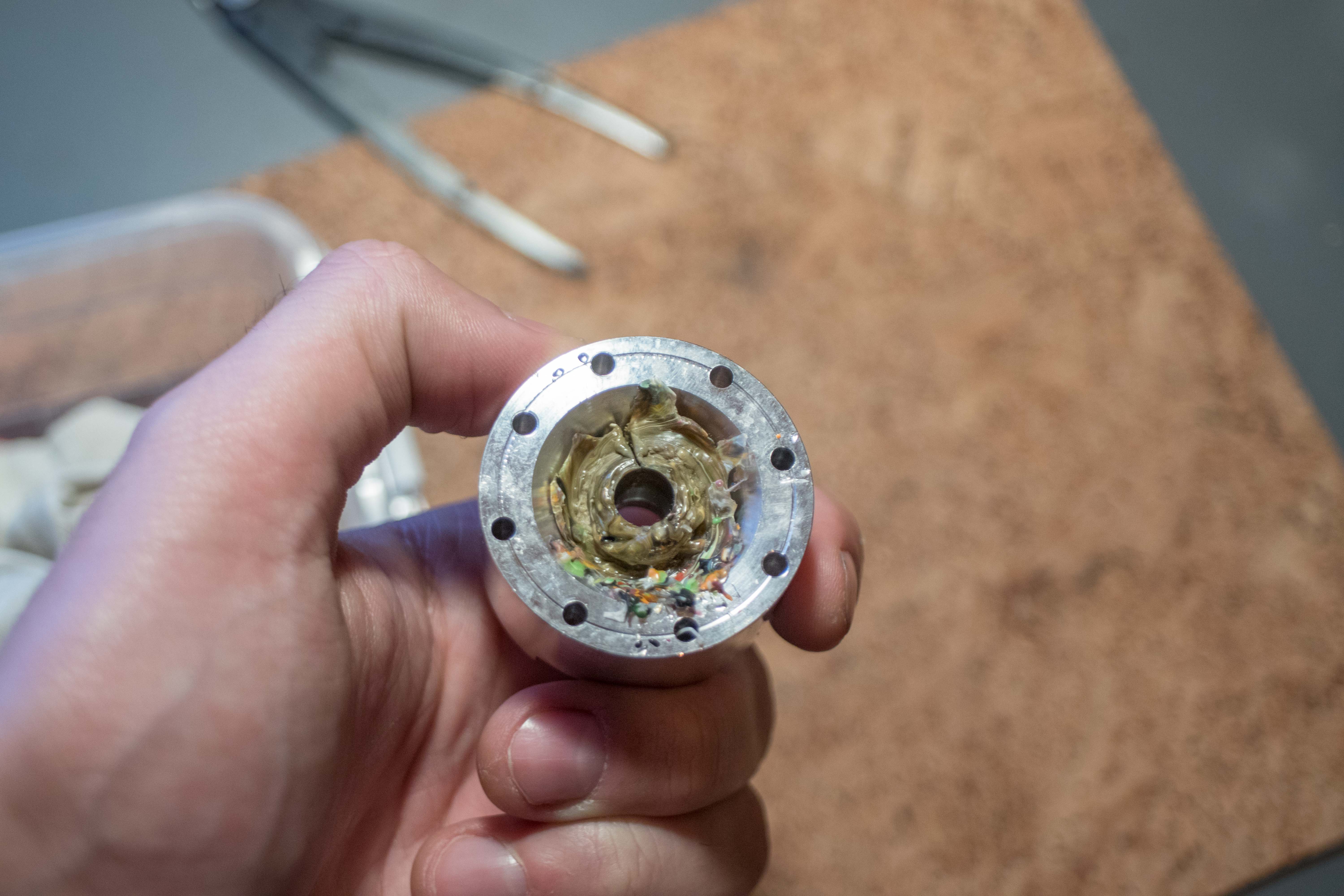
The shredded plastic which was fed into the screw melted too early and became molten in the hopper. This melted plastic stuck together and would not feed down into the screw. This happened because the heat from the hot end ( the nozzle end) wasn’t radiated away fast enough and thus was able to travel up the melting tube housing the screw and reach the hopper.
All the colours melted into a light brown.
Second Test
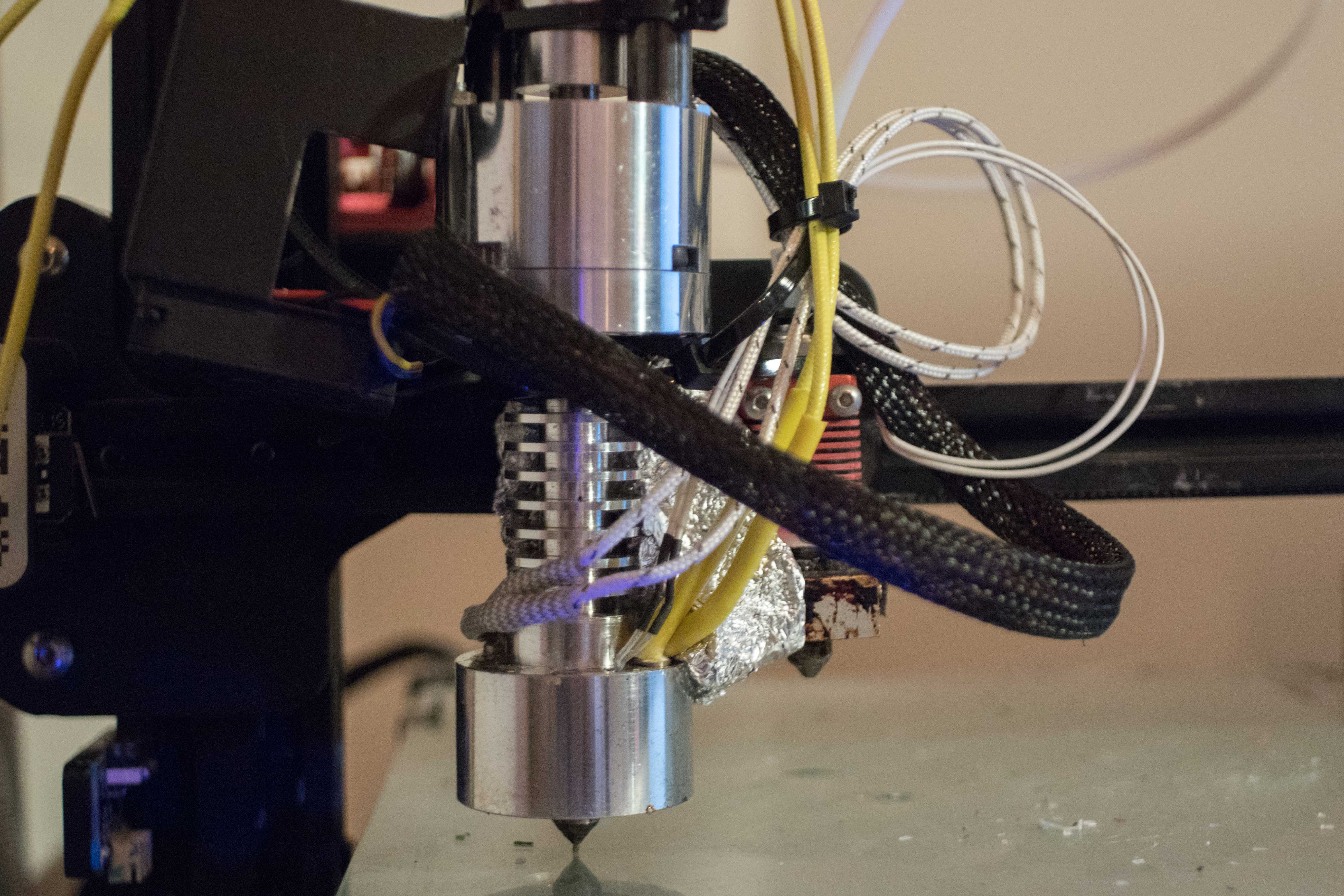
Modifications
Cuts were made to the melting tube to increase its surface area and thus its ability to radiate away heat.
The fan from my printers stock printhead was attached with cable ties for extra cooling.
The 3D printed PLA spacers which directly contacted the hopper also began to melt so I replaced them with some steel tube.
Results
After preheating to 230C the printer took about 15 minutes, with the screw turning and the hopper filled with the finest blended PLA I had to test with, the first extrusion occurred
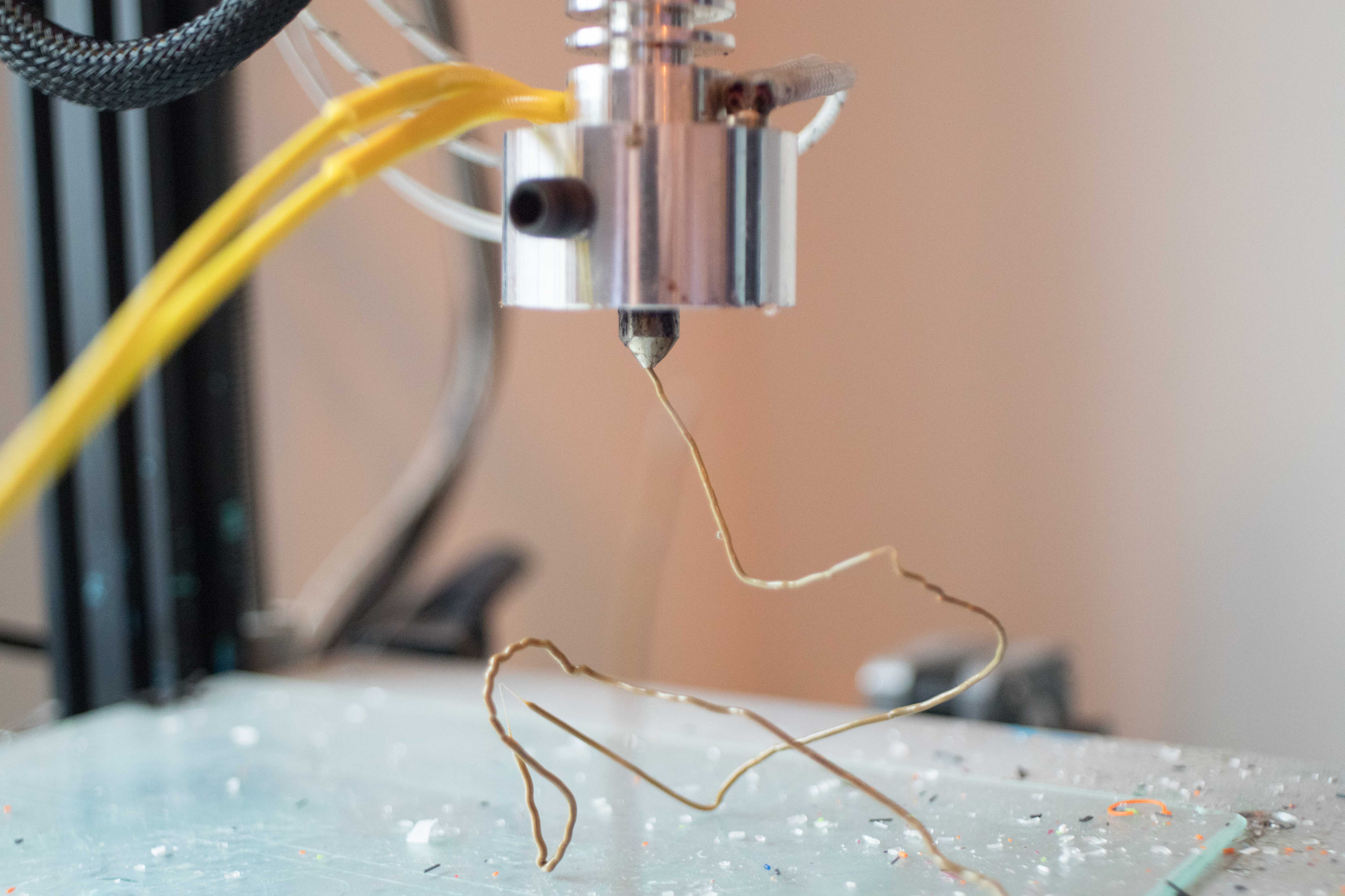
The extrusion was quite uniform although variations in its size could be seen in the form of bumps. The plastic melted evenly as can be seen by the even brown colour which is a good sign.
First Print
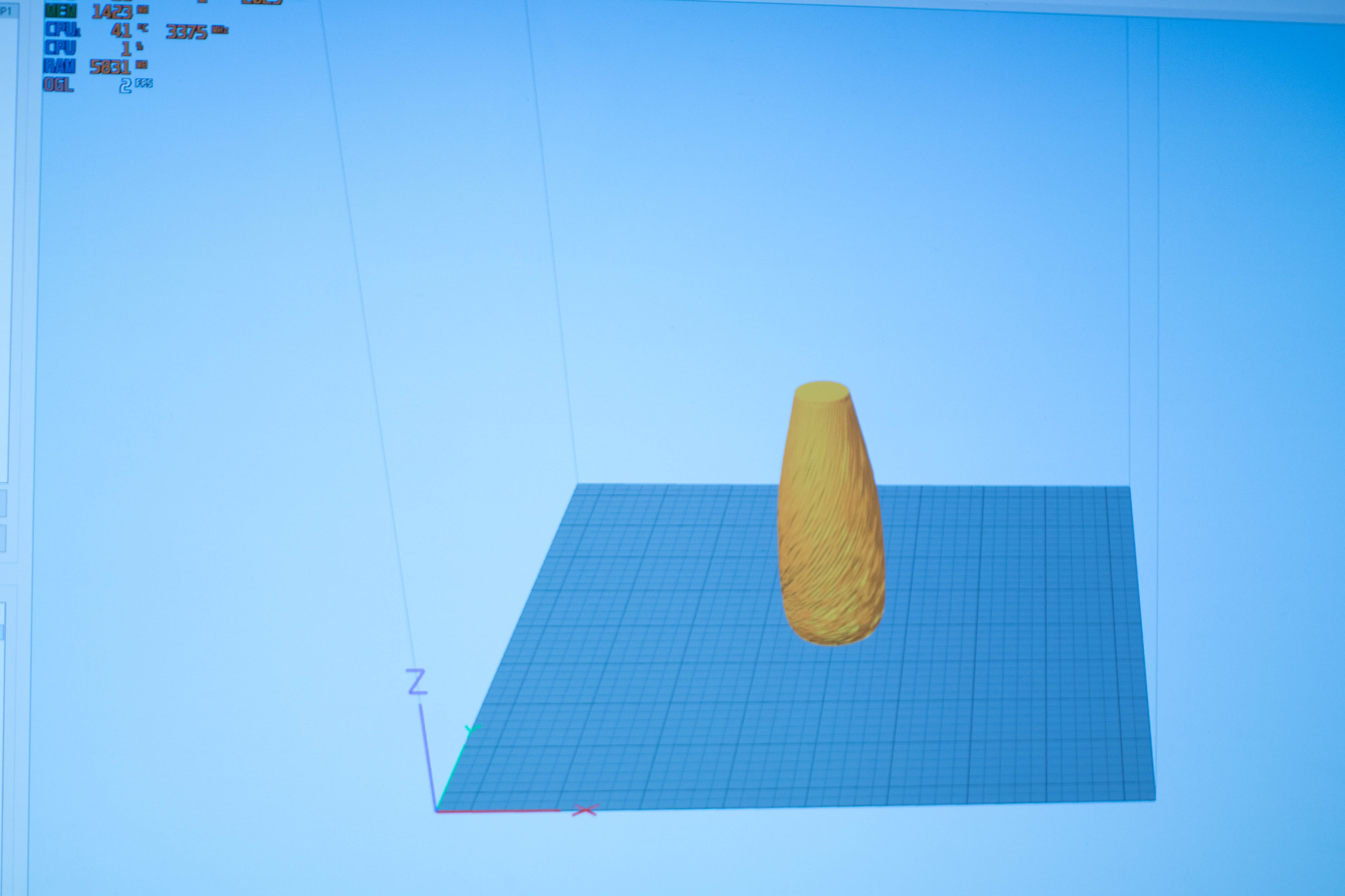
I decided to attempt to print something with the recycled plastic. Here is the model used:
Results
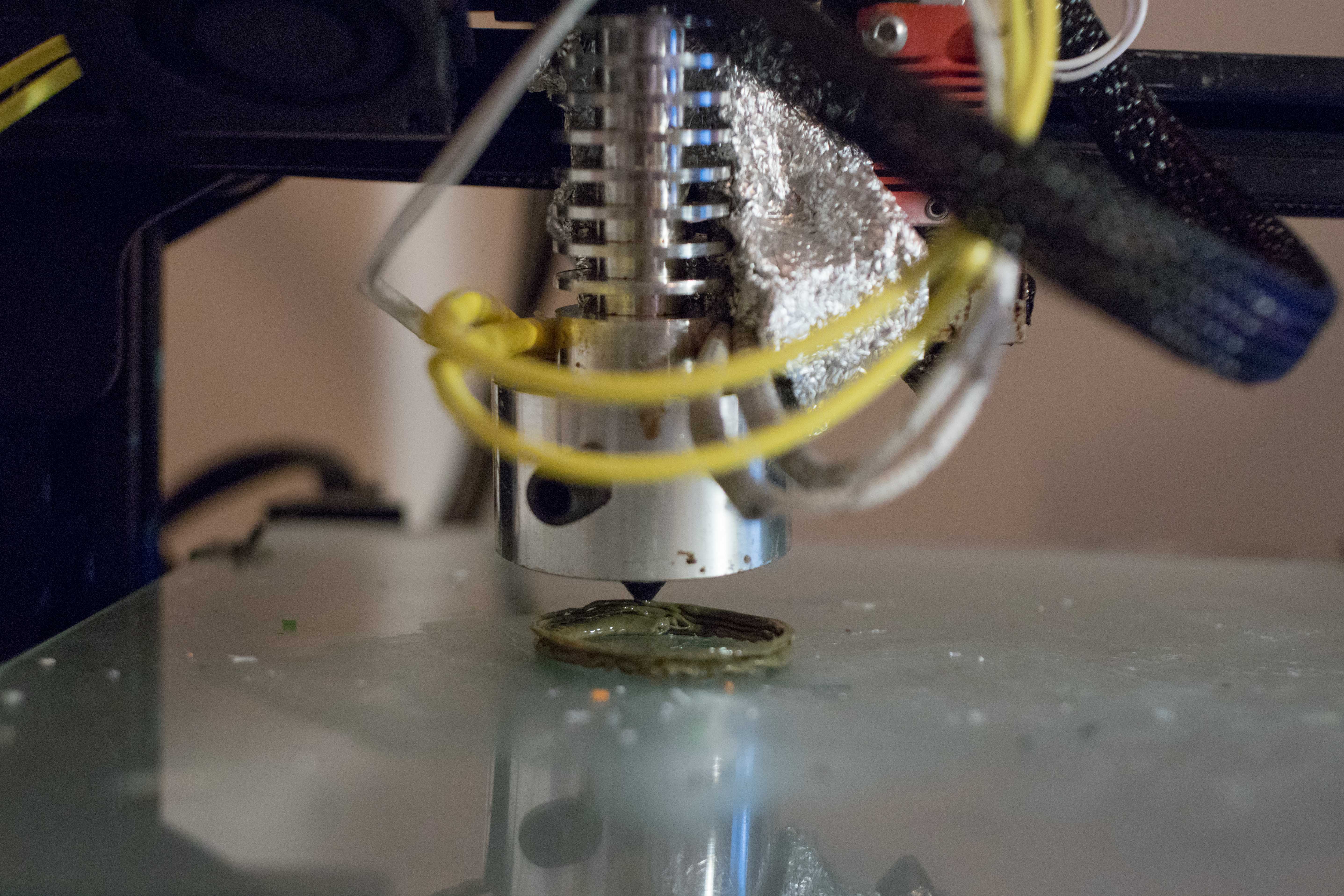
The attempt to print an object went less well than the first extrusion. The flow was less even but was printable for a time until it eventually jammed.
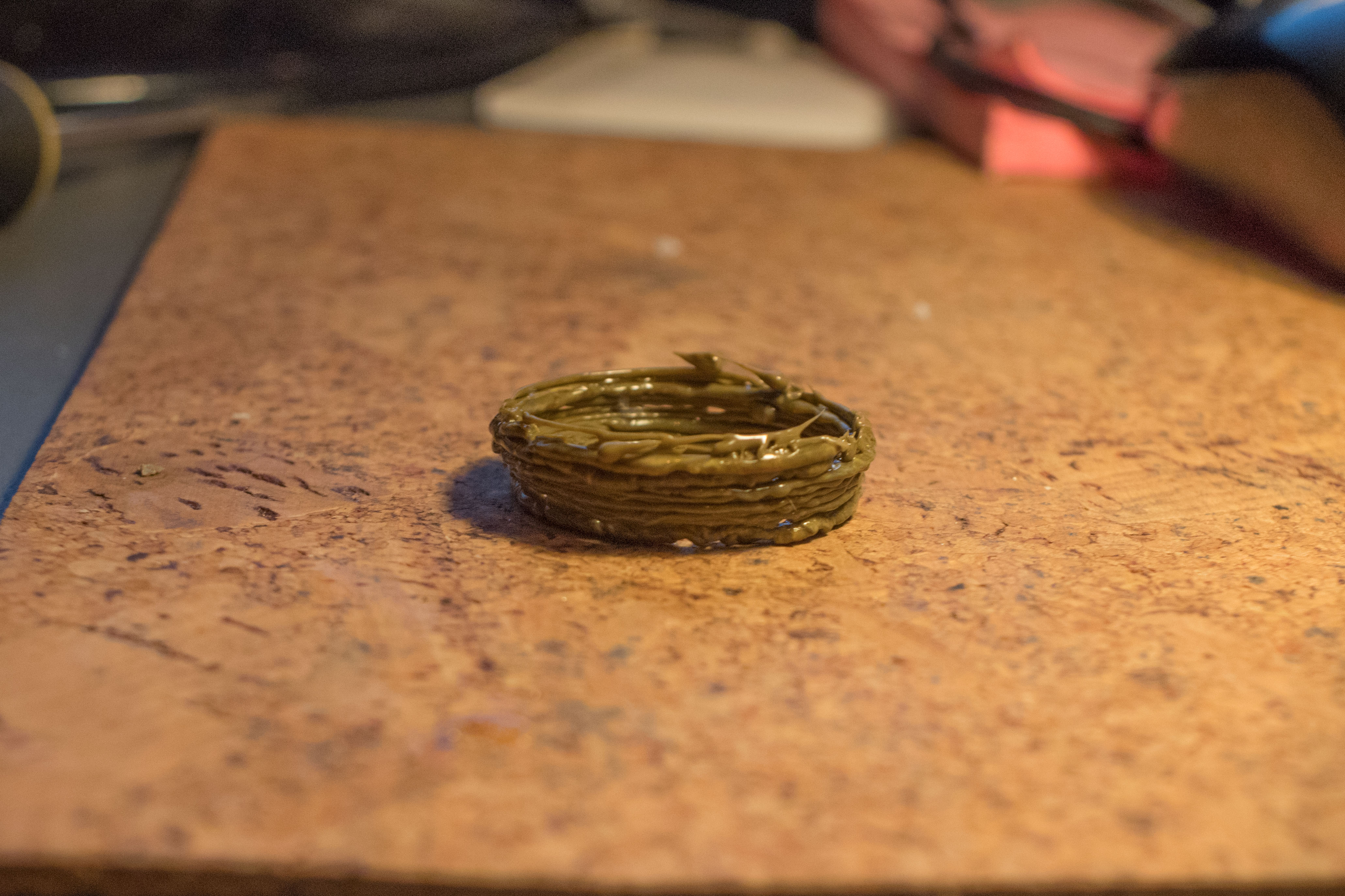
Conclusion
There are things which I think are happening to cause the jam:
The main factor being that I ran out of fine granulated/ powered plastic which I had used for the first extrusions and was now transitioning to the coarser plastic in my supply.
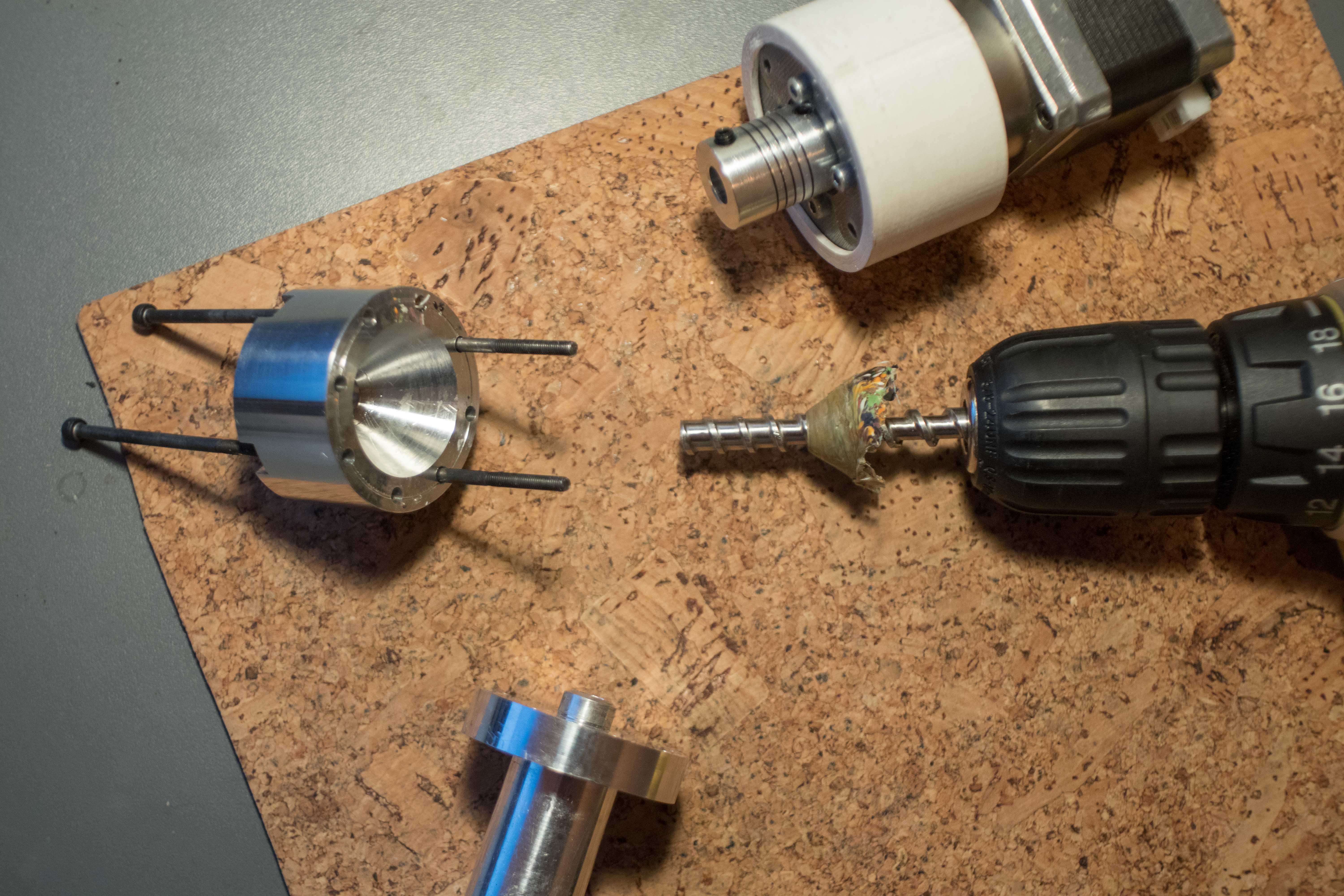
The secondary factor being that the screw is approximately 25mm shorter than the chamber it sits in. This is part of the design and allows the plastic to melt together thoroughly before passing through the nozzle and it also allows a buffer between the screw and the nozzle which means the screw pressurises this molten plastic which then extrudes through the nozzle when pressure exceeds the surface tension of the plastic over the nozzle opening. This reduces the needed torque to turn the screw as it is no longer in a sort of “1 to 1 ratio” with the extrusion rate. Effectively giving more granular control over extrusion rate. That’s what my puny brain thinks anyway but I’m no engineer.
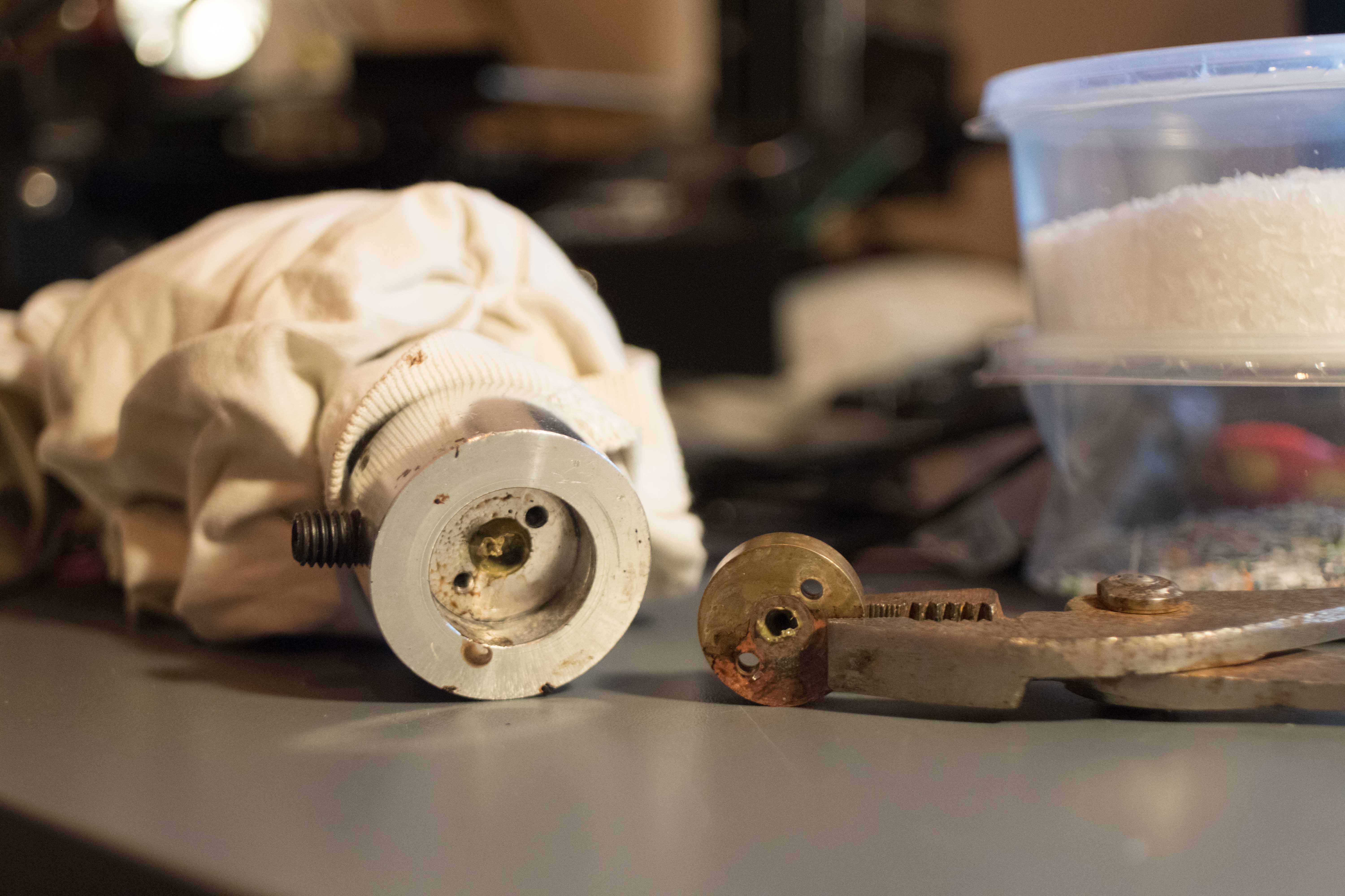
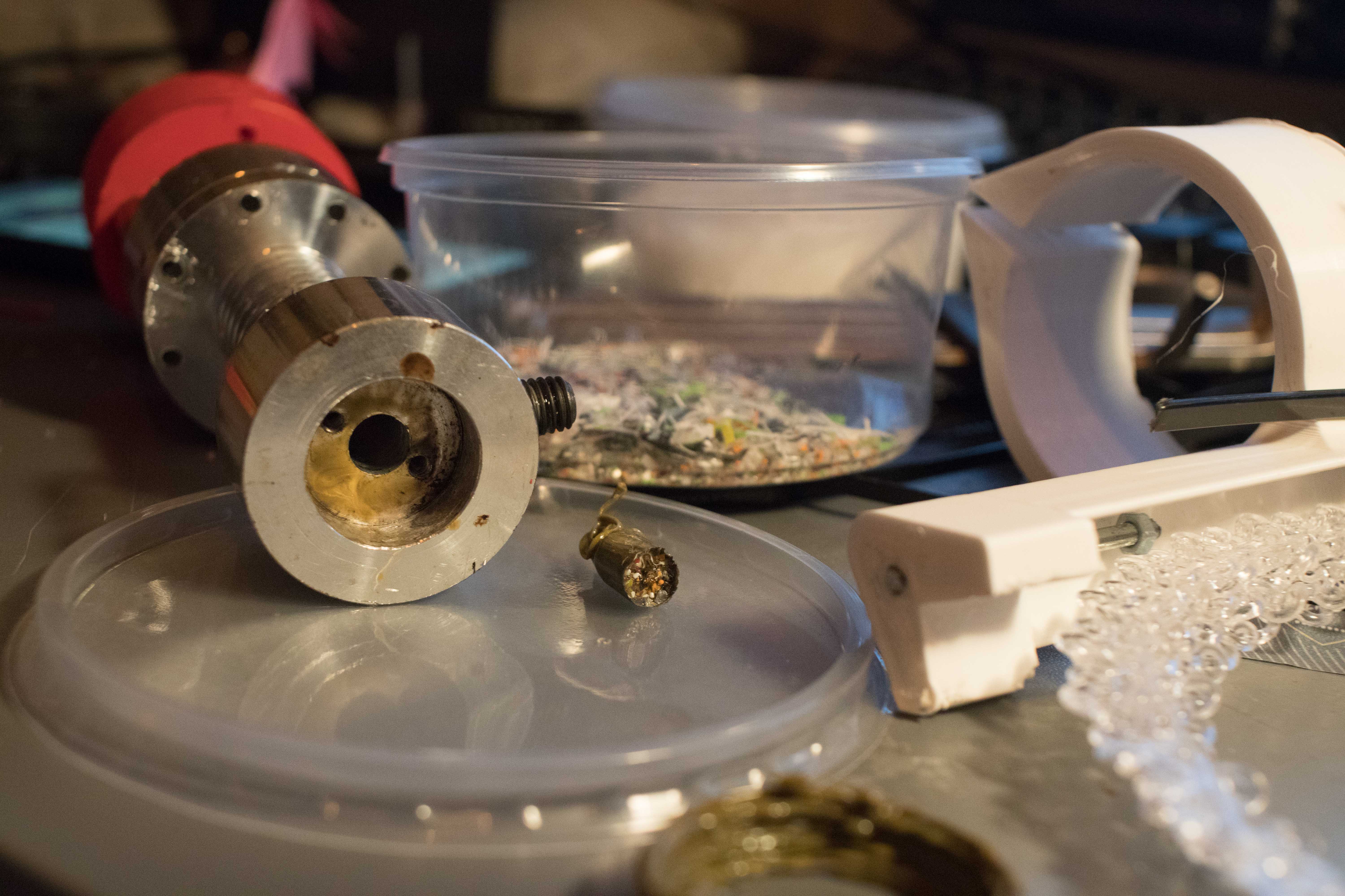 The plug of (formerly molten) plastic after removal from the melting tube.
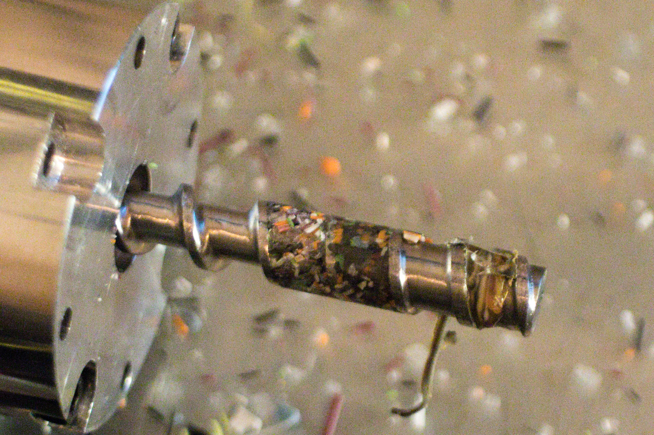 The screw after the extruder jammed
Next Steps
-
Find a way to make finer recycled plastic particles and test again to make sure the fine ground plastic really was the reason for successful printing.
-
Try lowering the tolerances to allow working with larger plastic particles. This could be done with a larger diameter melting tube or more easily with a smaller diameter screw or drill bit or by using the same diameter as before but with a drill bit with deeper flutes cut into it, allowing larger particles of plastic to feed in.
-
Try adjusting the distance between the end of the screw and the beginning of the nozzle to see how it effects operation.